
- Barham 2 -
HMS Barham 2 – Tyler
5.5 units, 26 seconds, British Dreadnaught battleship
The Queen Elizabeth class (Barham, Warspite, Queen
Elizabeth, Malaya, Valiant) is the best or second best ship in the hobby. The only downside is 26 second speed. It
otherwise has good beam, weight, size, usable turret locations, dual rudders
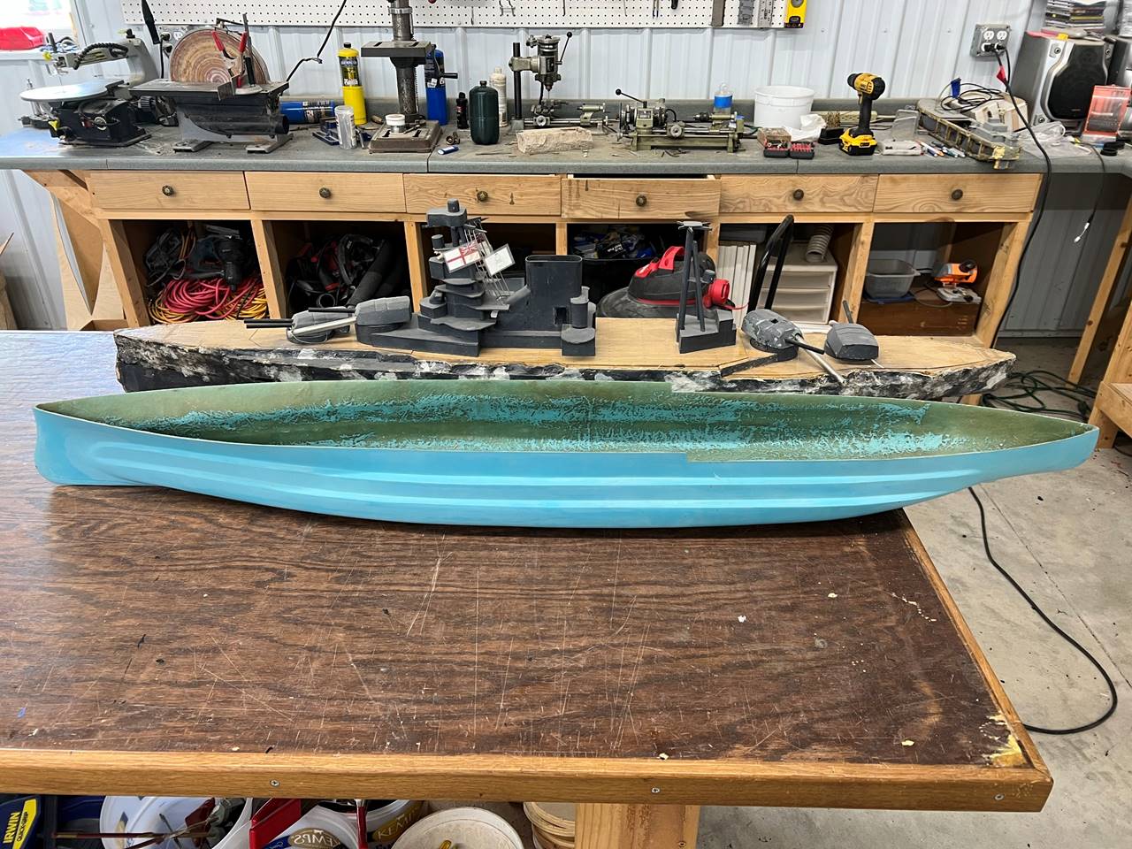
and 4 shafts, firepower. Ralph Coles built a beautiful fiberglass hull of the
slab sided variant of the Valiant. The real life ships had a long life span and
were heavily modified throughout their service history. For the purpose of our
hobby, the heavily casemated version is the best version and I modified the
hull back a generation or two by building the casemates out of wood and cutting
out parts of the fiberglass. I had previously built this ship and wanted to
build a second for my son. As such, I had the ability to copy what worked and
modify what should be improved.
Since this is a copy of an existing highly function
ship, I took direct measurements from the Barham 1, used the same plan set, and
directly copied my methods as much as possible.
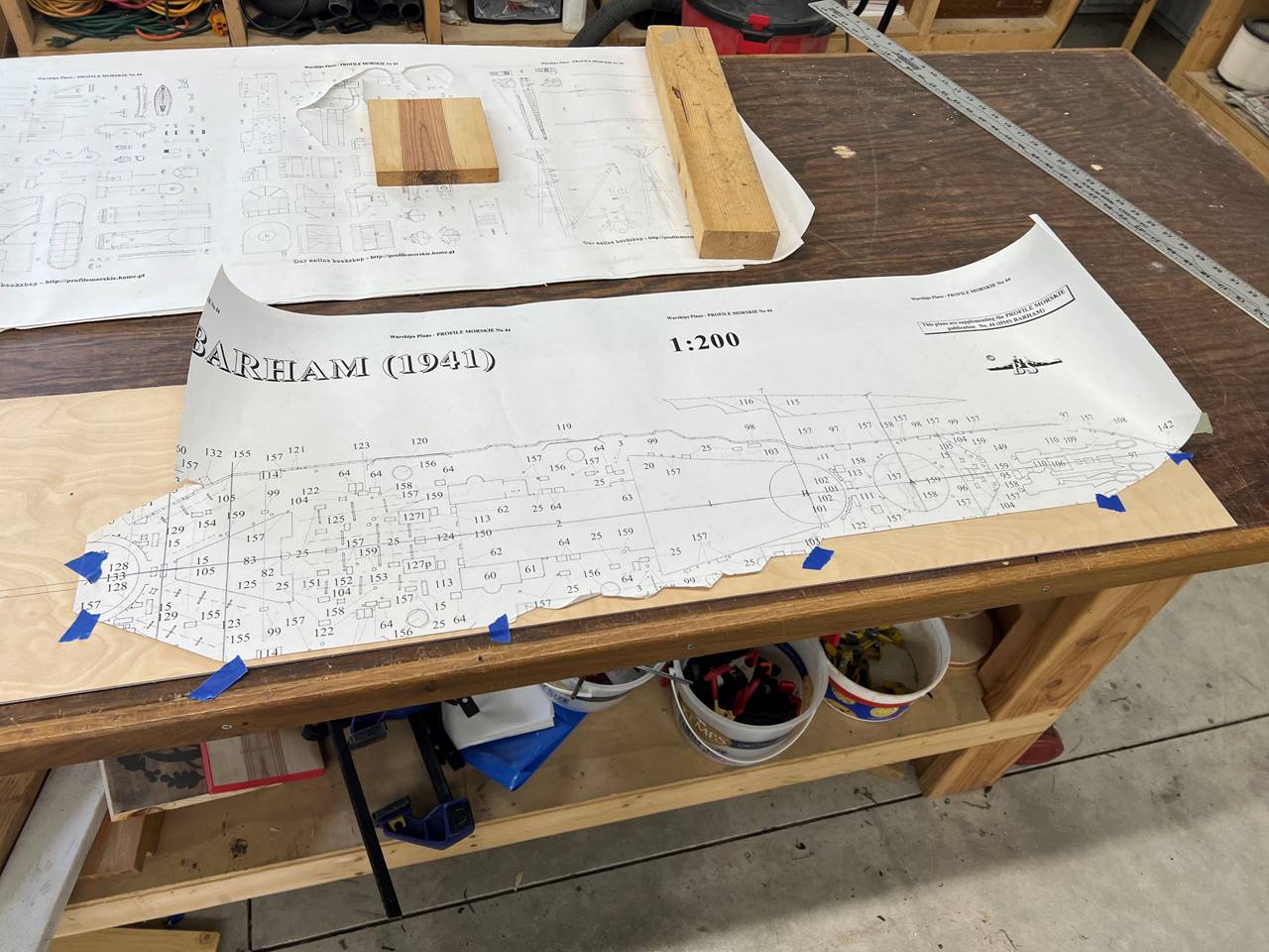
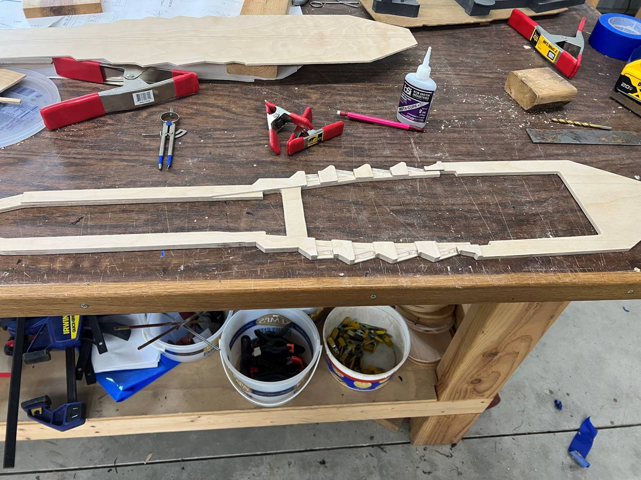
The deck was cut by tracing the paper plan directly on to a piece of
wood with the centerline drawn.
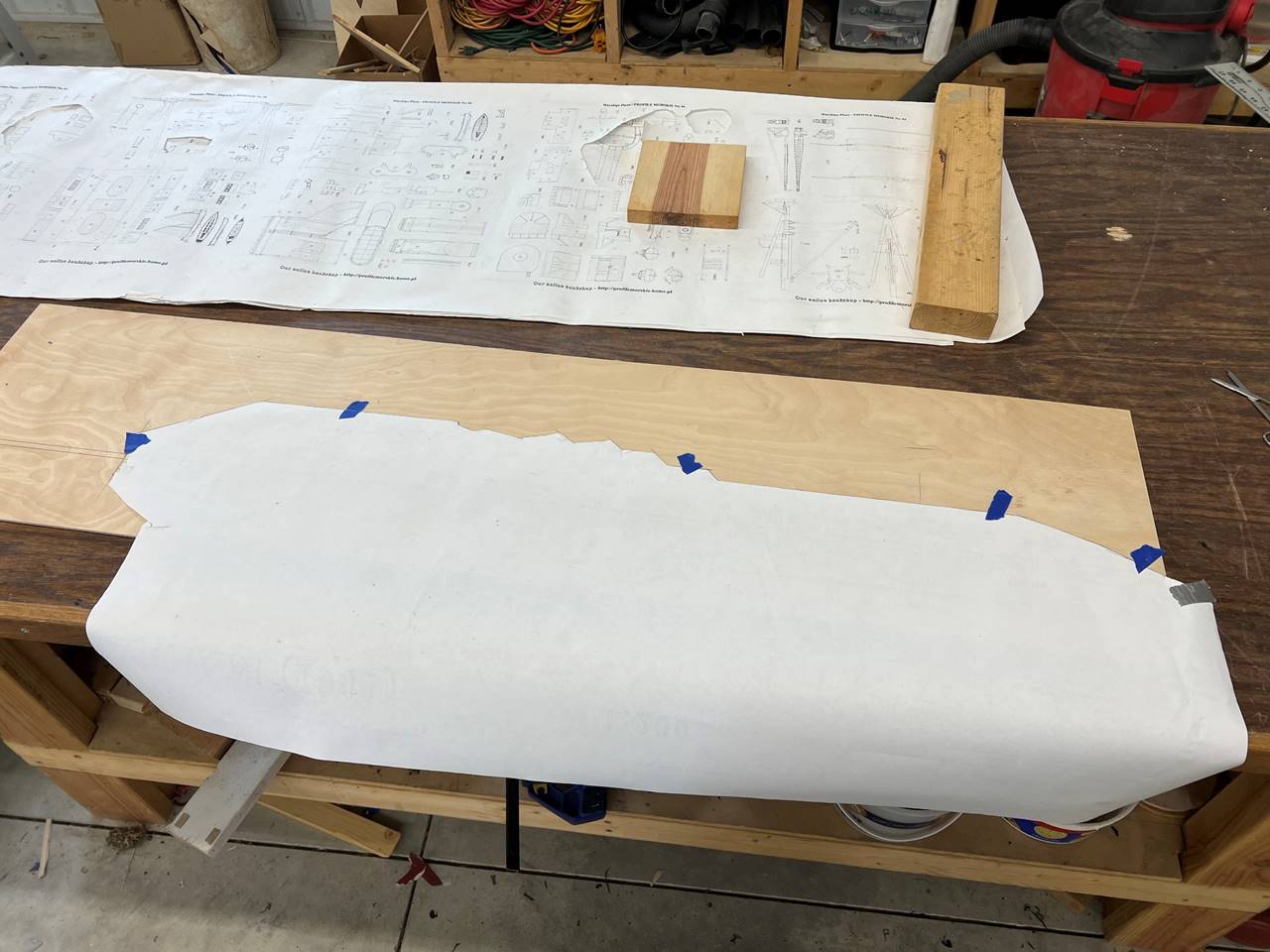
To keep it as symmetrical as possible I flipped the
plans rather than cutting out both sides.
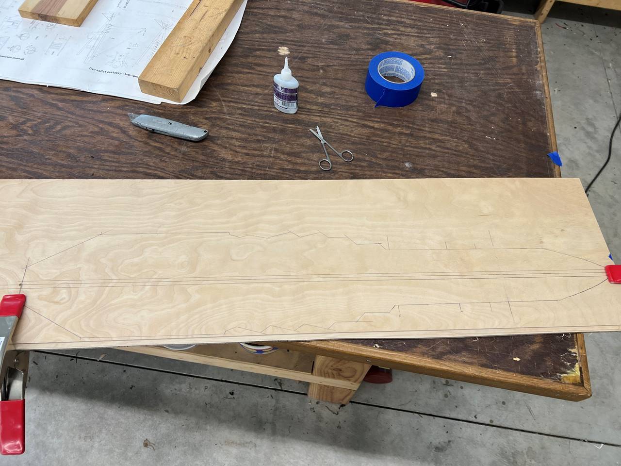
The deck was penciled in. I got the wise idea to tack
glue the subdeck section to the deck and cut them out as one. It worked fairly
well.
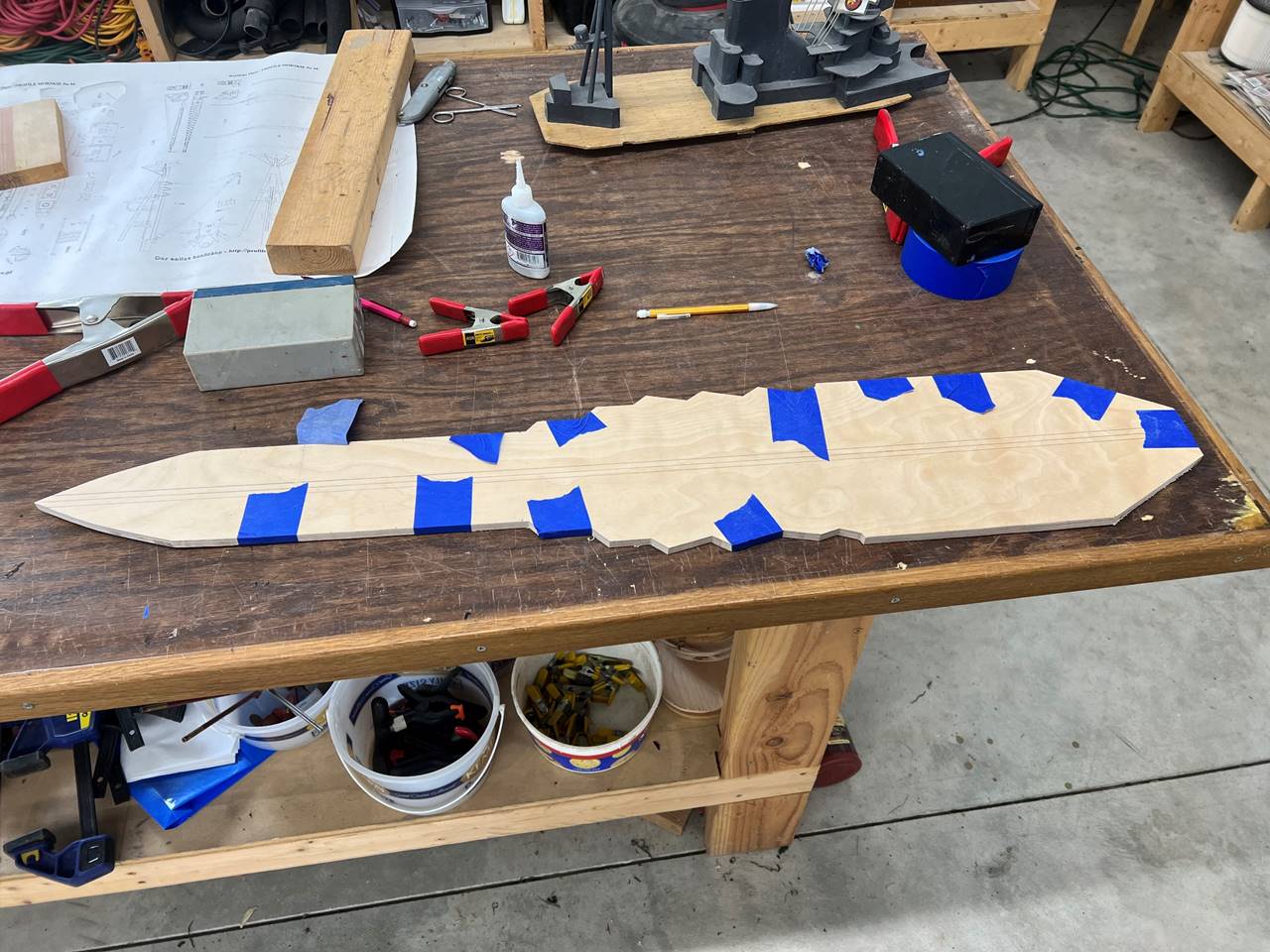
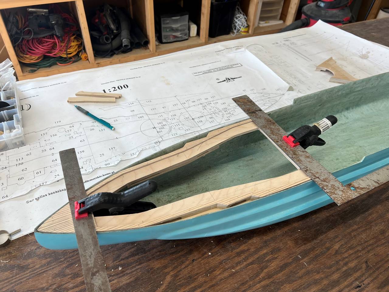
The two pieces of wood tended to slide a bit, I had to
use glue, clamps, and painters tape to keep it steady as I cut.
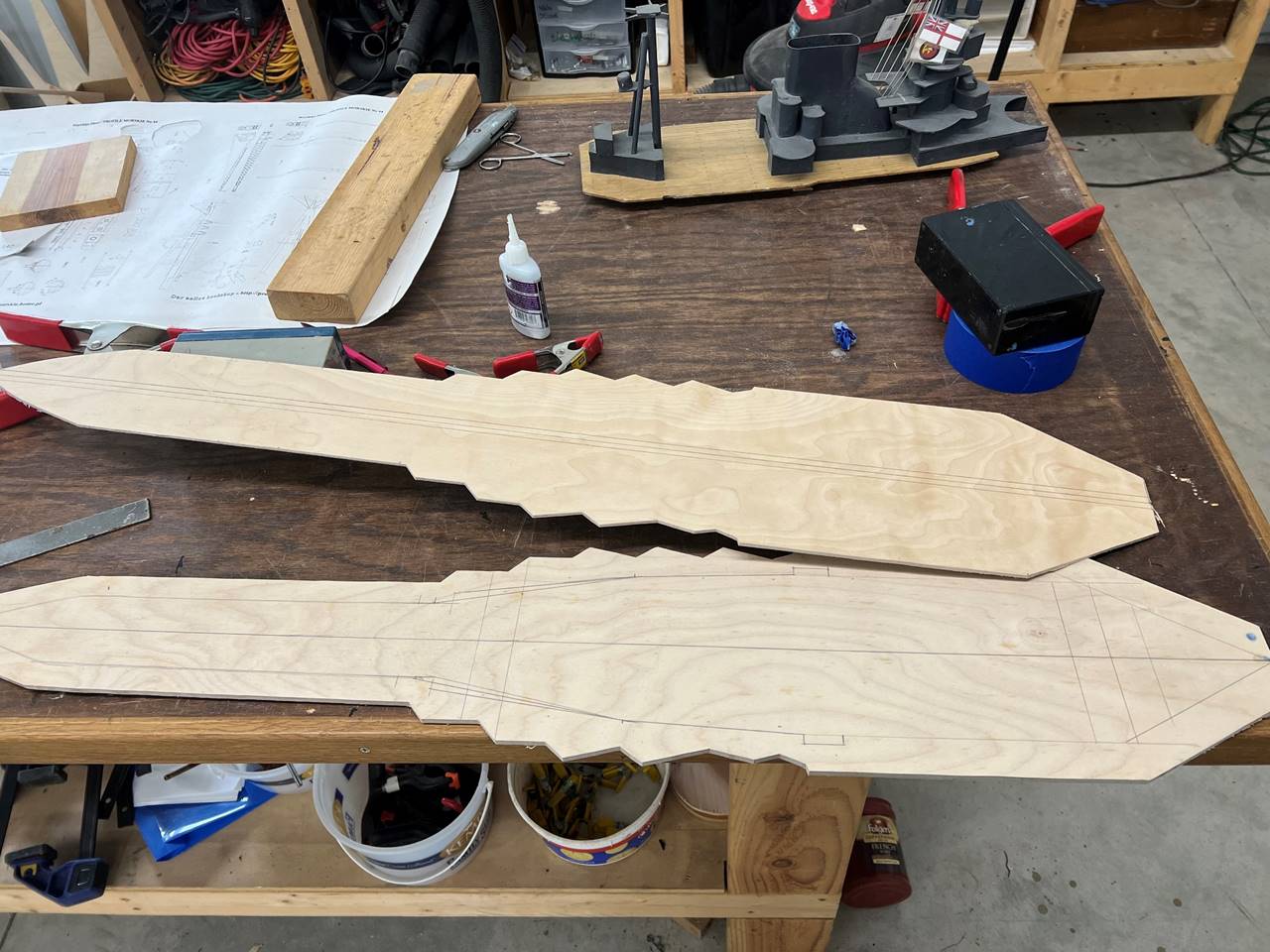
The deck and sub deck were separated and the subdeck
was marked for cutting out the interior portions.
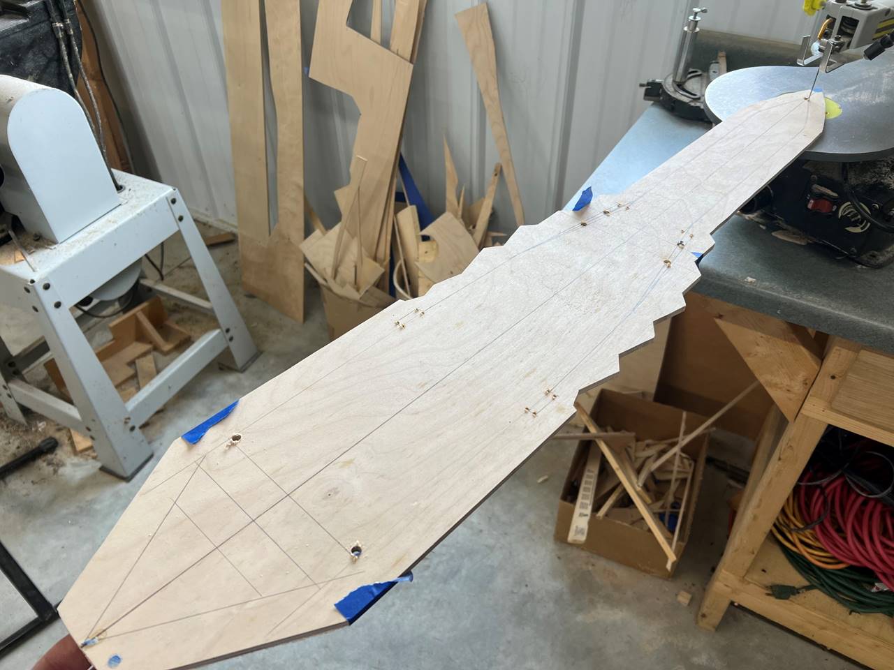
It is best to drill holes at the turns to make the
scroll saw not over-cut. I usually tape the under side to make ripping of the
wood less problematic when cutting across the grain.
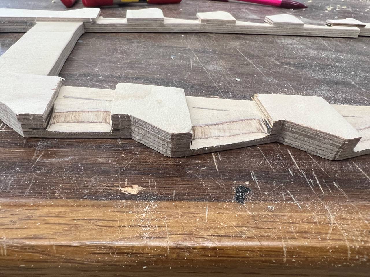
After the sub deck was cut I glued
pieces to the bottom side to build the height up above the lower part of the
casemates. Since the total deck thickness can only be 1/4 inch in this part of
the ship I could have used a 1/8 inch deck and 1/8 inch subdeck, however I used
a 1/4 inch subdeck and sanded back to 1/8 inch along the outer edge in order to
be legal.
Wider angle picture showing the
pieces being glued into place.
This picture skips forward several steps.
You can see the casemate level deck was glued on to the bottom of the assemply.
The stern deck portion was completed in a very similar fashion. The outer edge
of the deck/subdeck/casemate deck assembly was sanded to fit within the
fiberglass hull at the appropriate width (you need to be sure to measure often
as the fiberglass hull can deform/stretch/collapse to some degree making just
tracing the hull alone at times an incorrect width, be sure to measure
frequently throughout this process. It is also notable that I used pencil to
draw on deckplankigns because they look pretty.
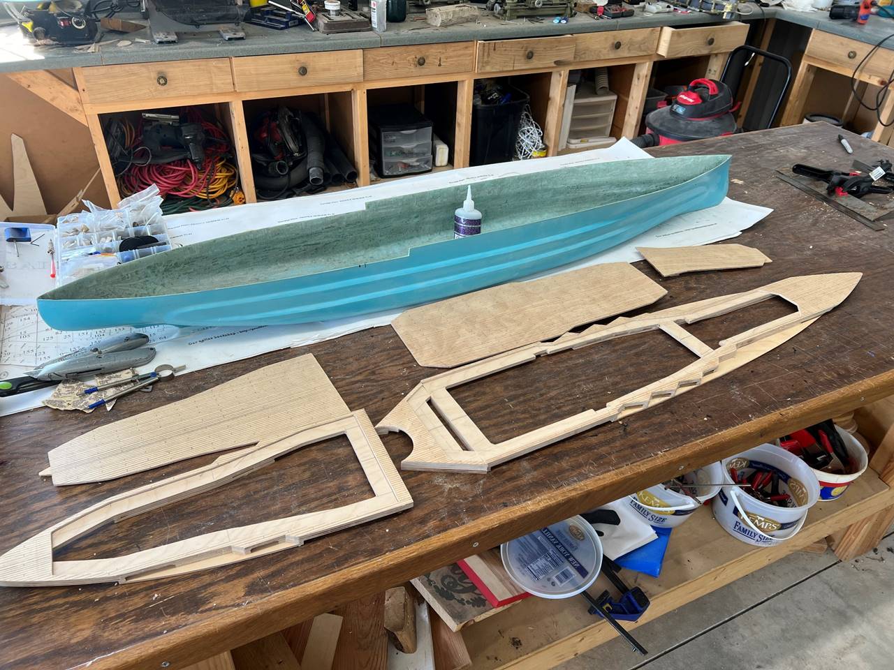
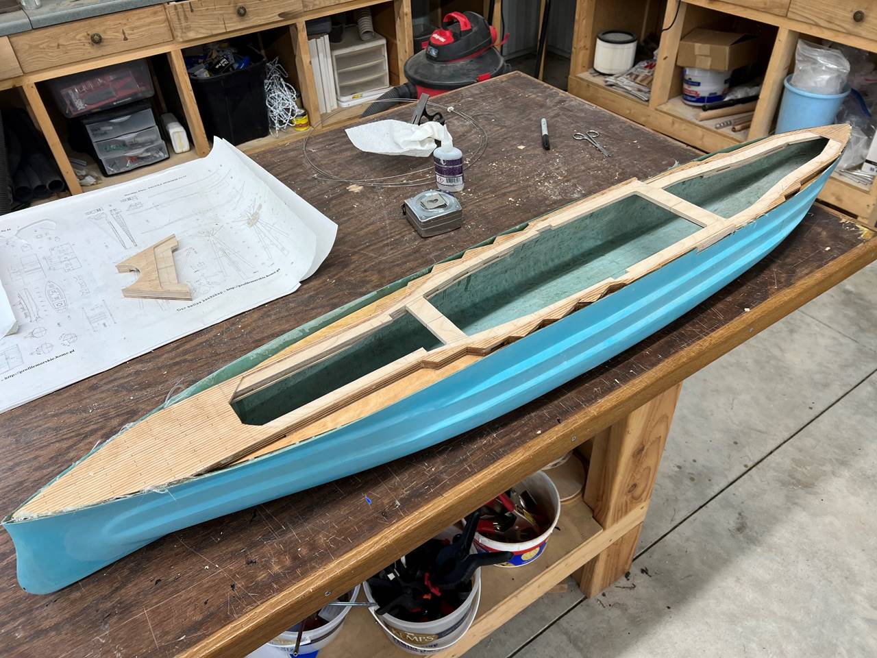
Here is the assembly wedged into the
hull.
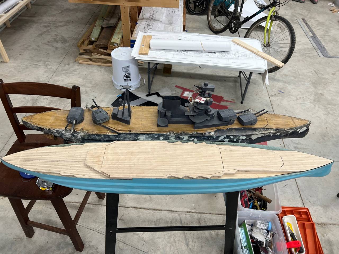
This is with the decks on and sitting
next to her sister.
When gluing in the deck/subdeck assembly
I like to try to keep things as flush as possible by clamping stright edges on.
I used the same method for the bow portion.
This picture was taken after the
assembly was first tacked in with super glue but then more permanently adhered
with West Systems epoxy.
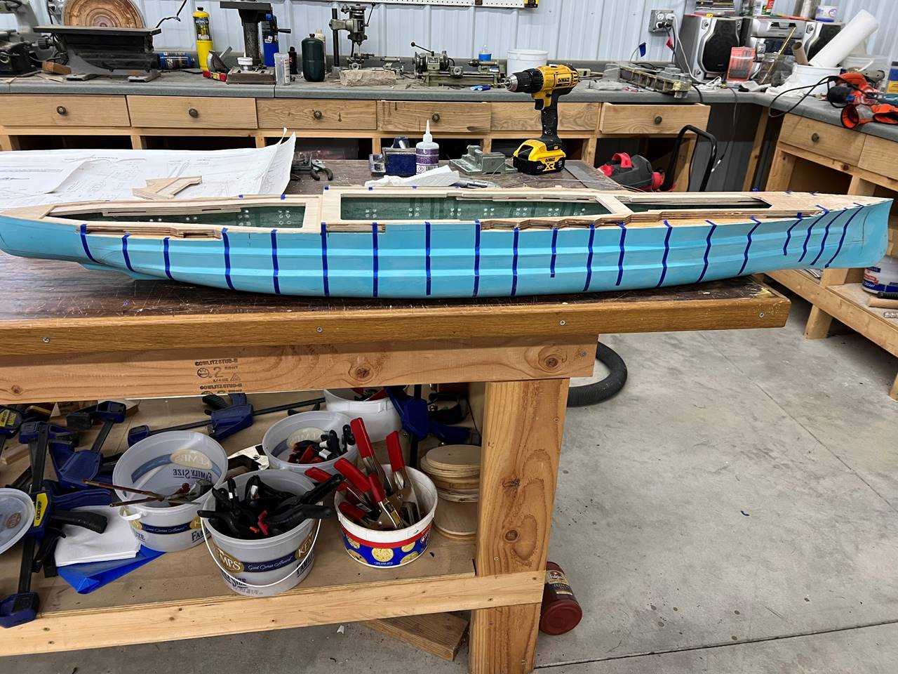
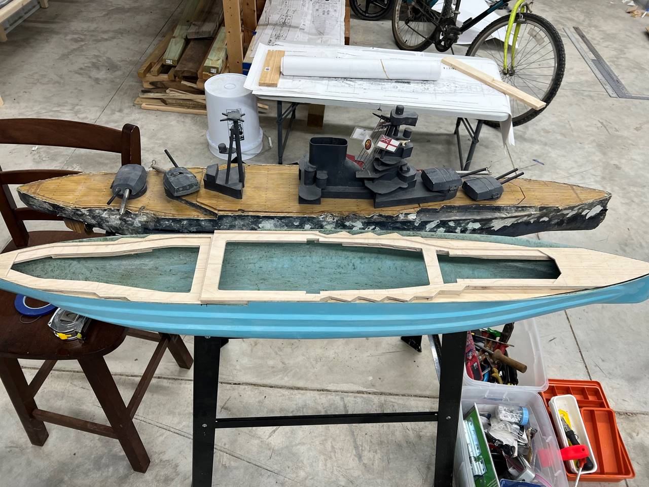
I cut the excess side of the hull
material back to expose the casemates. I marked the ribs late in this build
because I knew where they would go based on the prior version. In general, I
would do this step much earlier in most builds. The theory here is to put ribs
moreso in the bow for increased protection where the ship sticks ot of the
water more. I also lined up ribs with casemates to make the open area in the
casemate smaller. A lot of people put denser rib collections in areas they will
be shot more, such as next to sidemounts, the bow, and in this ship you could
do more ribs in the middle area astern to the casemates as well since this is a
relatively exposed area in the QE.
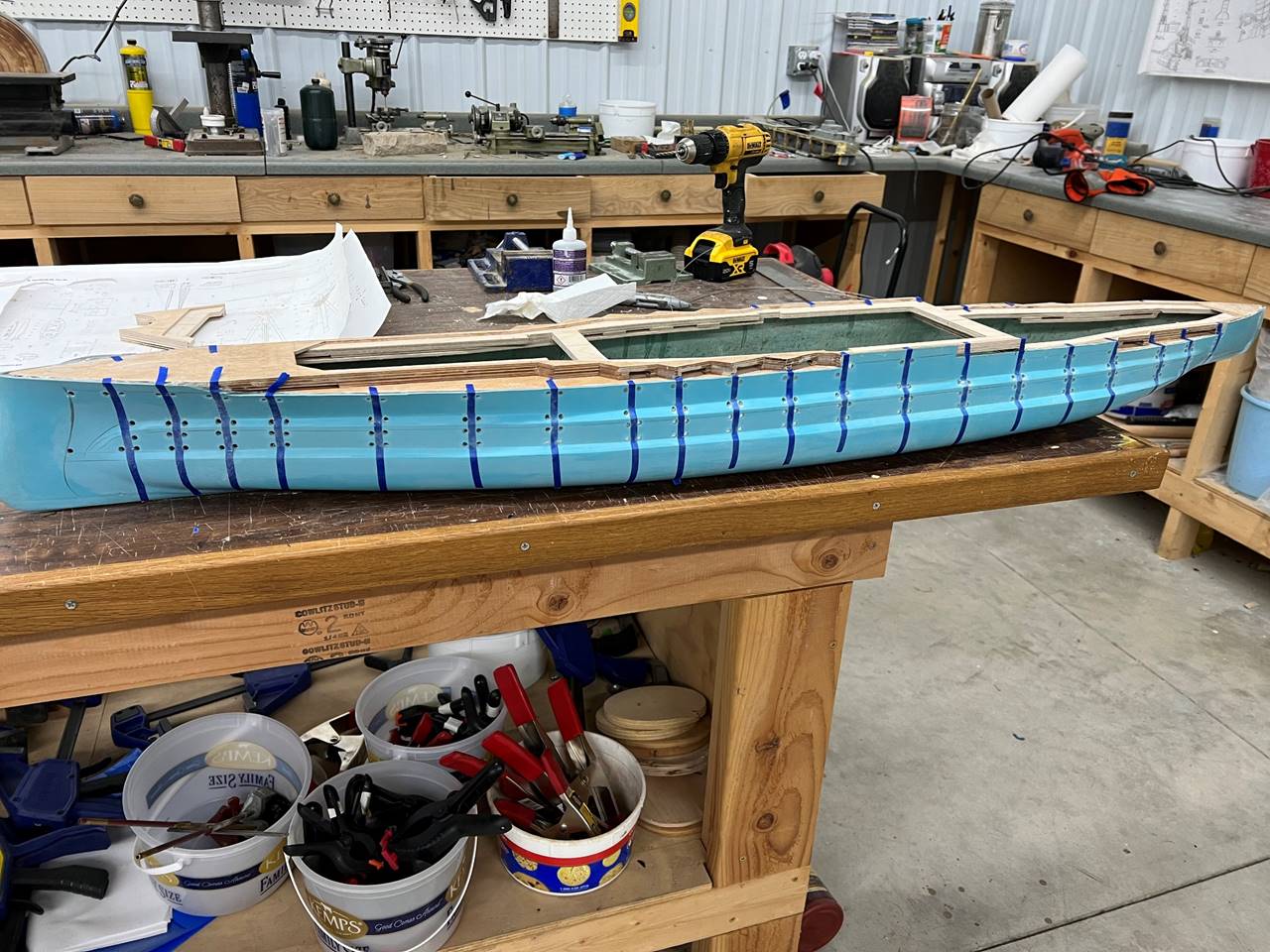
Pre drilling the corners before cutting
out is highly advised.
It seems to happen frequently with my
builds, but once again I got distracted from putting together good in-process
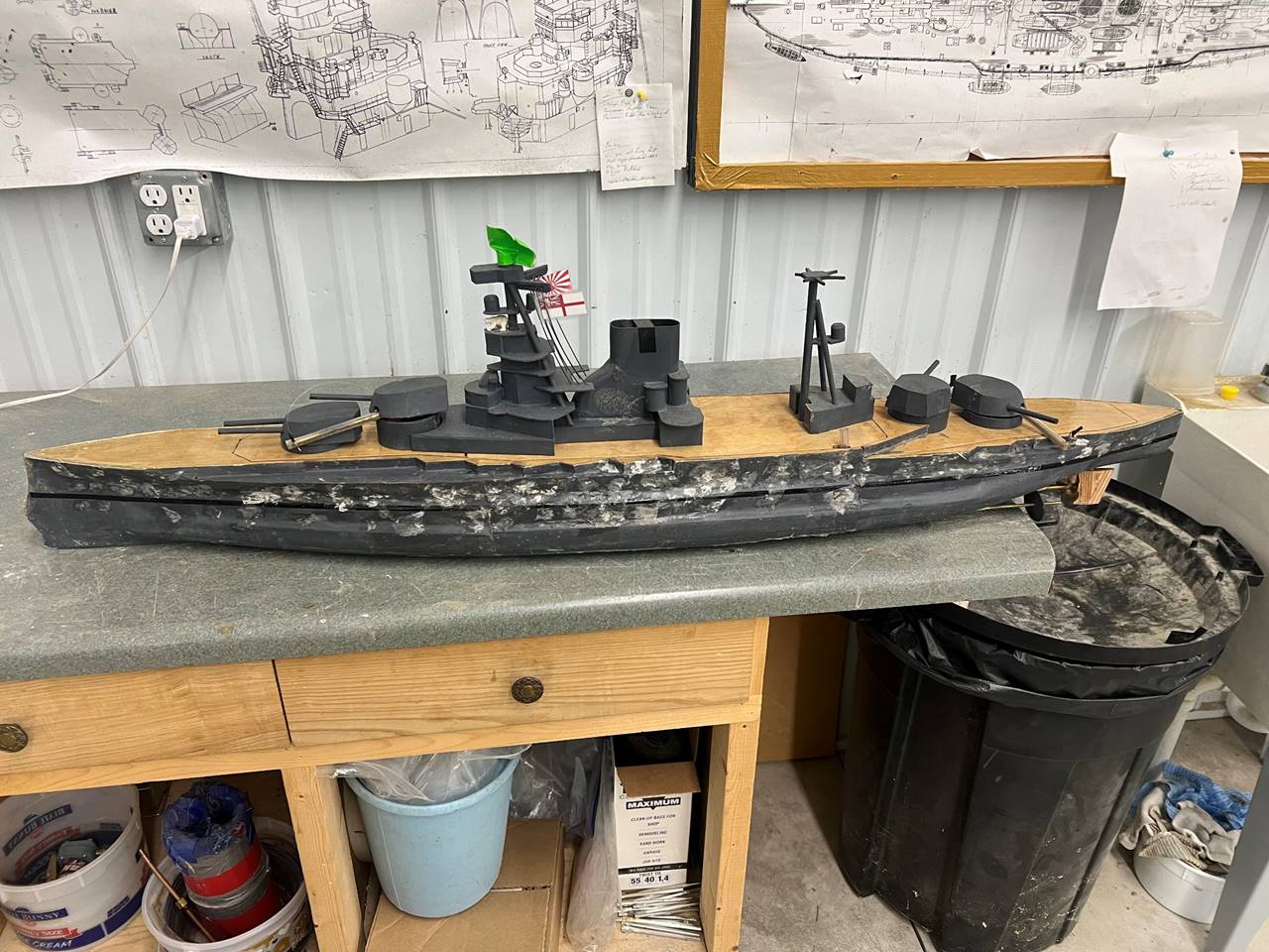
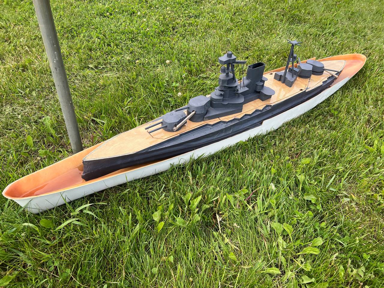
picturs so some as completed pictures will have to suffice. The ship battled for
the first time memorial weekend 2025, and after a few small tweeks was ready
for Nats 2025. These pictures are after her first Nats. Superstructure is
sheets of ABS. Turrets are a mold I made, poured with a flexible rubbery
urothane. The ship has 2 full unit pumps, 2 stern sidemounts (the superfiring
is 75 rounds) and a down angle bow gun (funny gun).
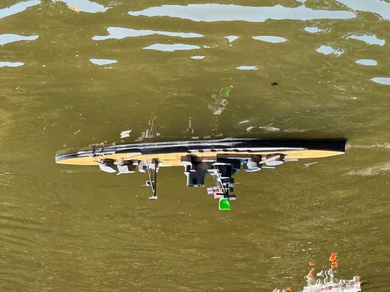
This pictures is too funny not to
include. This was float testing inside of a Jean Bart hull before Nats 2025. I
did have to take the drag disks off but otherwise she fits.
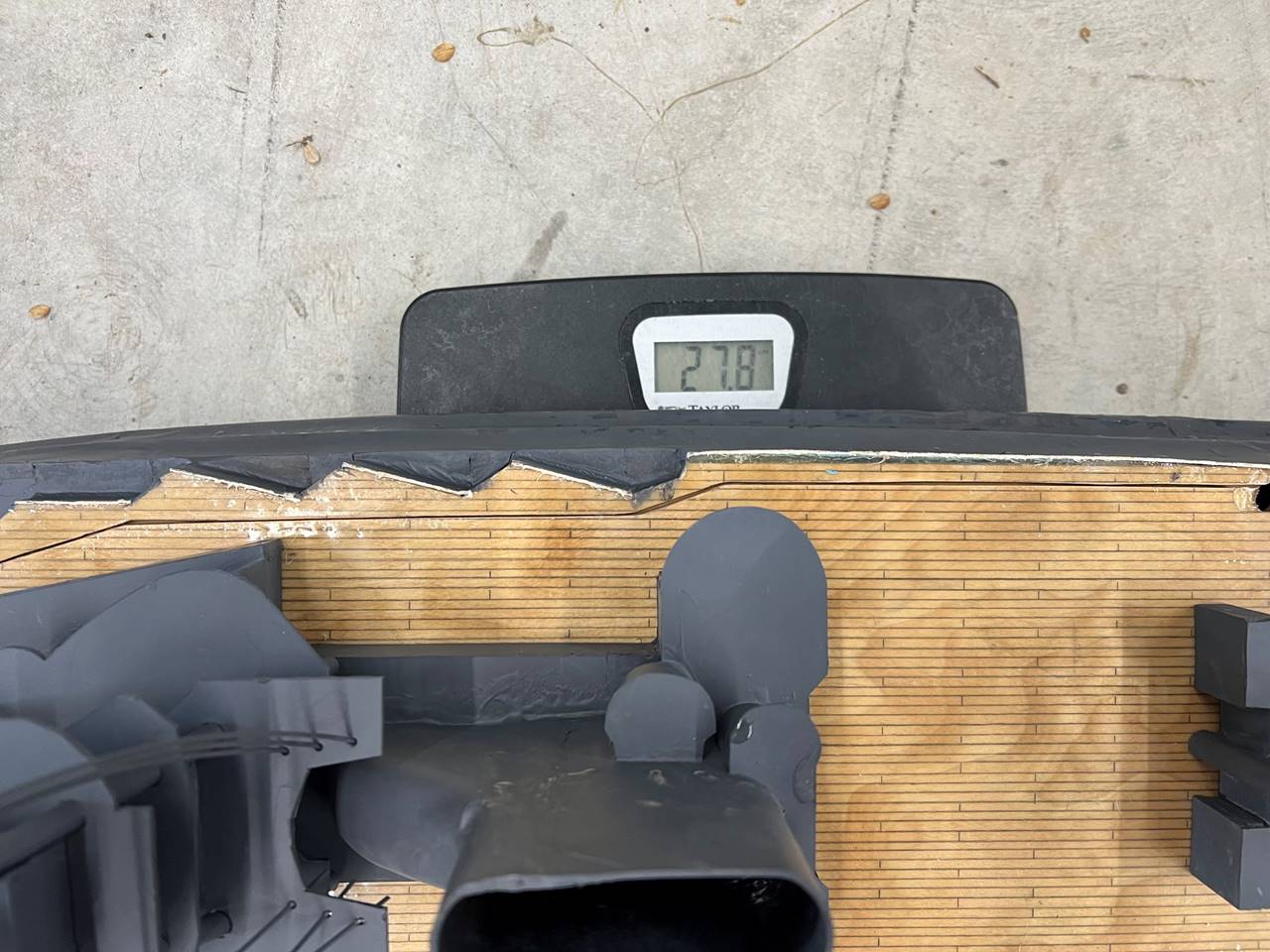
Ship weight is 27.8 pounds.
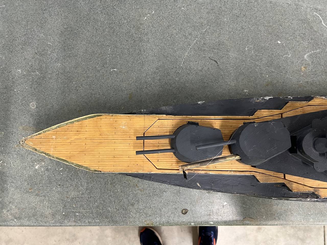
15 degree off angle depressed bow gun
can shoot below the water line.
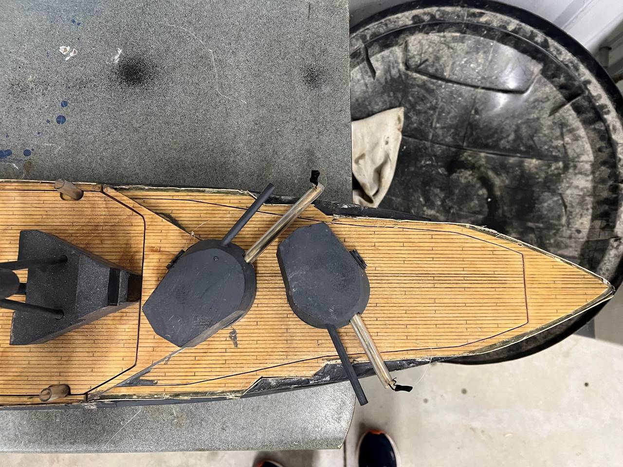
This is the business end. The underrated
benefit of using 2 pumps and not using twin stern guns is that it frees up real
estate for another stern sidemount. This ship has a stern deck that sits low to
the water, and is quite manuverable making for a very dangerous stern gun
setup.
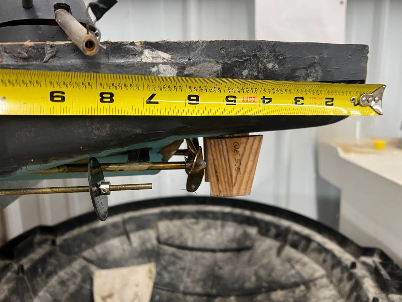
Props are between 5.5-6 inches from
the stern, with rudder post at about 4.75 inches. The ship has 4 drive shafts,
two inner powered and the two outer with drag disks. The twin side by side
rudder shape is slightly different than the Barham 1 but the ships turn very
similarly and I’m not convinced either is supperior. This is a good look at how
little of the hull you have to expose to fire the stern most sidemount.
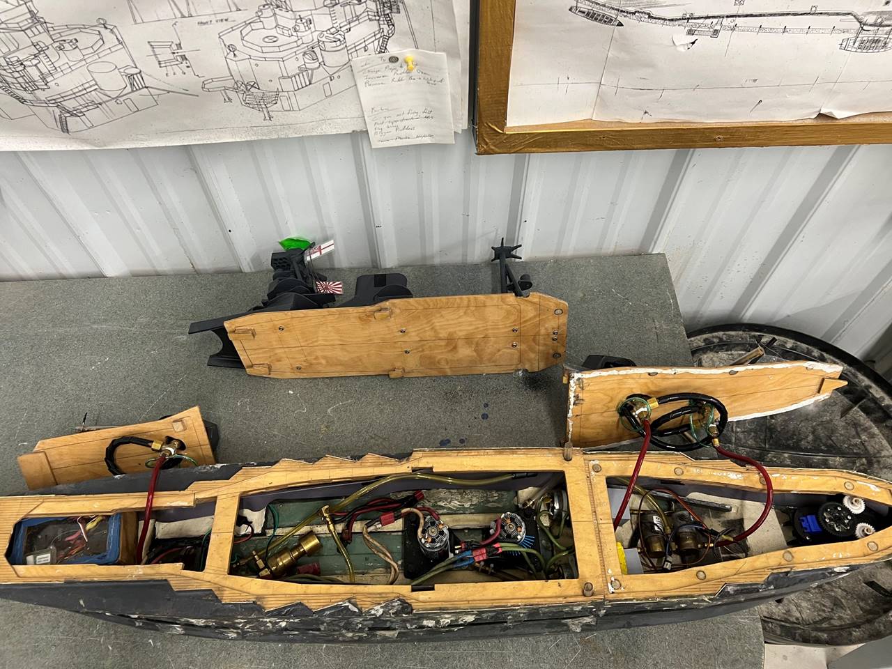
The middle section is removed for
routine battle access, ideally the bow and stern deck sections can stay on unless
heavier maintannce is required. The section has slides and locks which when
pushed forward keeps the section locked in place. Since there is overlap with
the bow and stern sections of deck as well, once this middle section is on, none
of the deck sections can be easily removed. I put magnets on the stern deck and
the back of the mid portion deck to help keep that section in place, there
seems to be enough friction and this is probably not necessary.
The front deck section also has
slides and locks, this is not going anywhere when the middle section is on
since there is super structer overlap and the deck itself abuts the middle deck
section. The back section also is held down when the mid section is on and can’t
come off. The back section however just has 1 latch in the stern most part and
magnets for the rest, a 1/16 thick magnet imbeded in the deck and a 1/4 inch
thick magnet in the subdeck. I applied white silocone as well since this ship
will ride fairly wet on the back deck when fighting hard, this seems to be very
effective at keeping extra water out.
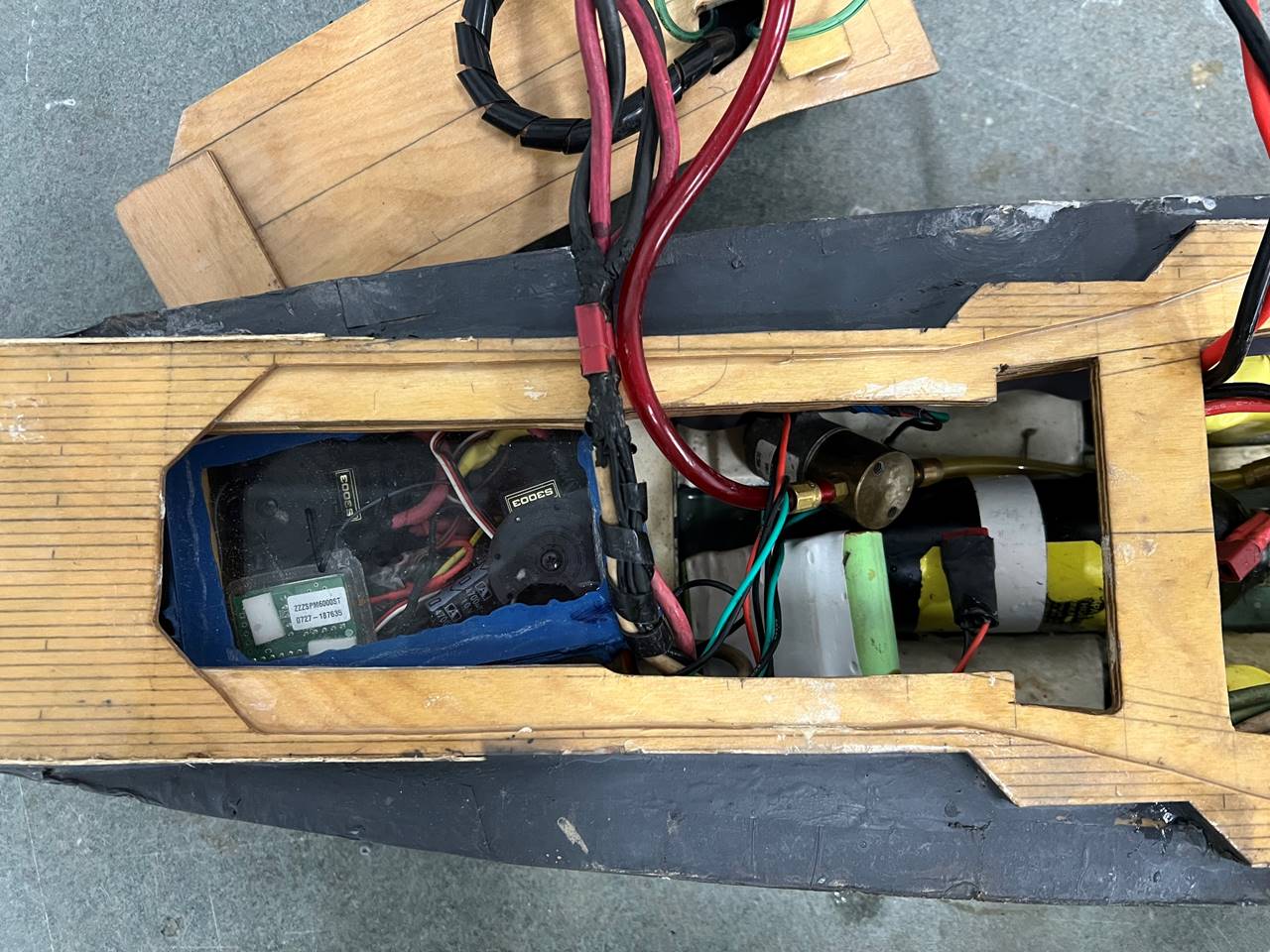
Under the bow deck sits the radio box
(which is admittedly old fashioned at this point), bow gun solenoid, back end
of the CO2 bottle, and a reciever battery. The radio components from this ship
were taken directly from the VU. Again, admittedly old fashioned but still
effective, this ship has a servo switching drive as well as the pump, it does
have solid state electronic firing boards for the guns. The VU origionally ran
20 amp hours main power alone and occasionally with hard battle would drop
voltage and go out of control. As such I opted to wire in direct reciever
battery power. Since the Barham runs 40 amp hours it is not necessary in this
ship to do this but has not been switched back over. Since it works fine I may
just leave it.

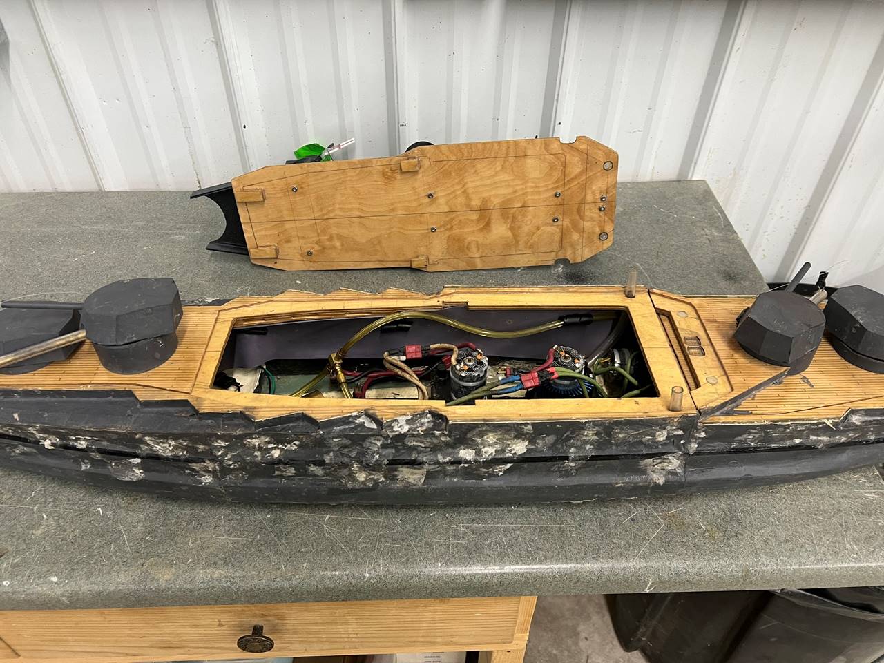
The middle portion of the hull houses
the four 10 amp hour 6 volt NiMH packs in trays along the outsides of the ship.
There is bulge water channeling, so these actually about 1 inch from the outer
portion of the hull. The two pumps are midline and sit in front of the motors. You
can see where the hose exits the hull. The CO2 bottle is a 5 oz, I actually
have a 3.5 oz bottle in this picture because the bigger bottle was misplaced
and I still wanted to take the picture. The Barham 1 has mostly run on a 3.5 oz
bottle but frequently runs out of gas, making the 5 oz bottle a better choice. There
is a red piece of plastic which holds the bottle in place.
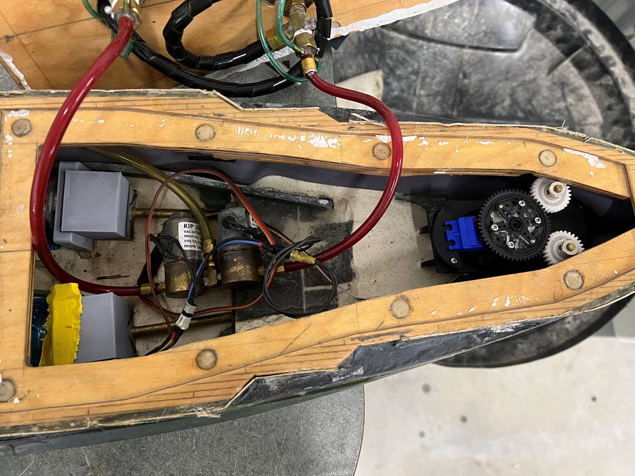
The motor mounts are printed ABS
knock offs of the old Traxxas Villain gear boxes which I so loved but are no
longer avaliable. Under the plastic boxy gray covers are the motor with a
pinion gear and drive shaft gear. The two stern solenoids are noted next to a piece
of lead used for ballast. The two rudders are driven with a water proof servo with
a gear mounted direclty on top.
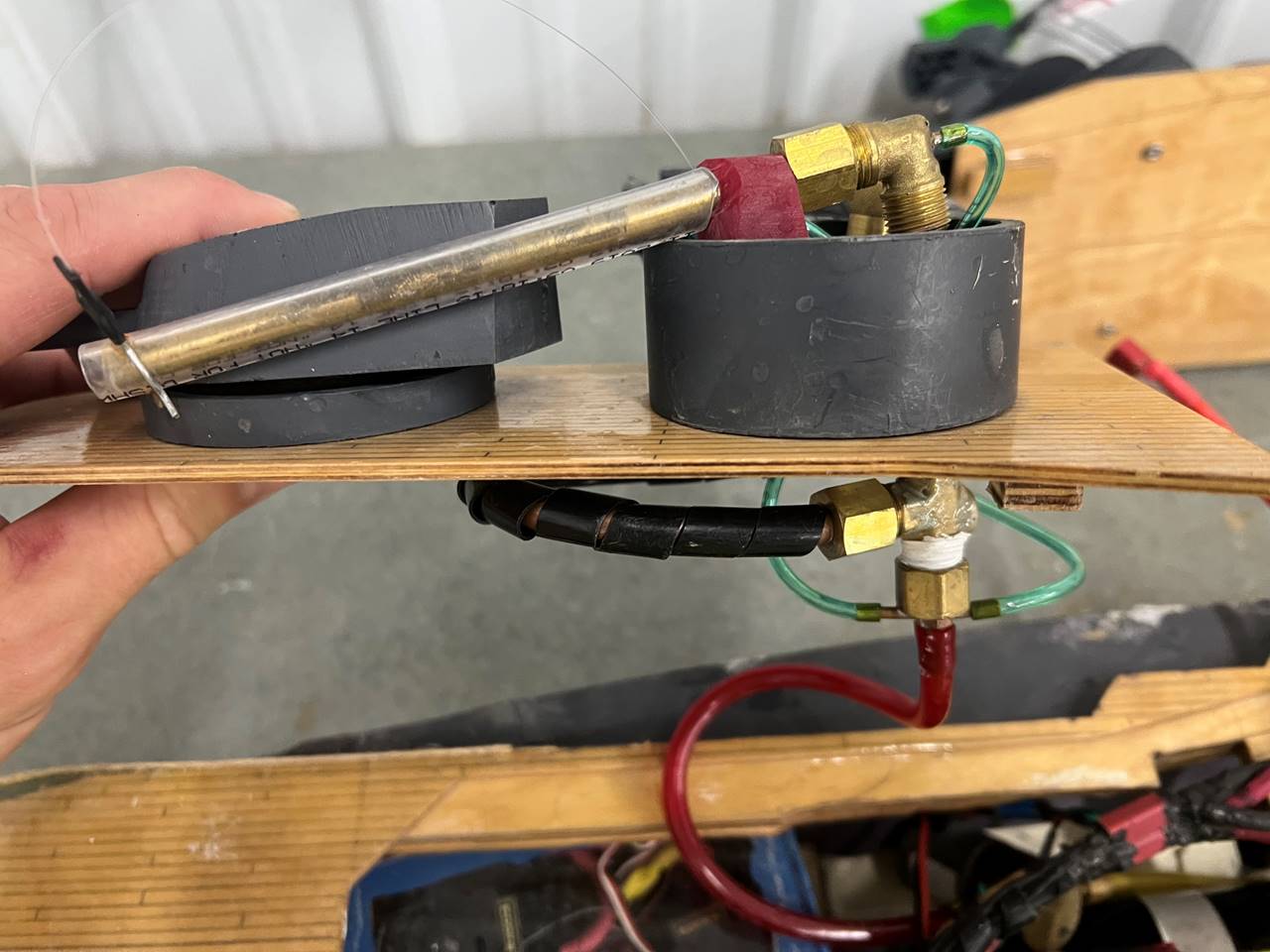
All of the guns on this ship have 1/8
ID gas in to the bottom with two 1/16 hose going to the back of the magazine
and back of the elbow. I have ben using epoxy to attach a small magent to the T
so misfires become less likely. The gun holders are a red plastic that is easy
to drill but quite strong. The magazines for every gun in this ship feeds back
to load in the same turret, you have to be a little careful with bend angles
but usually this works well.
Here is the ship at Nats 2025.
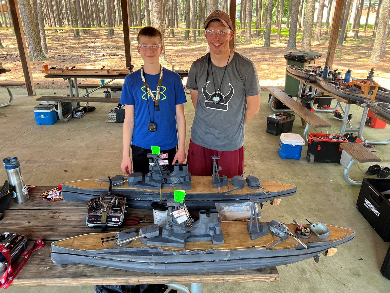
Father and son.