
- SMS Derfflinger Build -
SMS Derfflinger – Tyler
(launched 2008)
4.5 units, 24 seconds, German Battlecruiser
The Derffligner was my first
capitol ship. It is a wood hull built from a set of plans. Prior to this I had built
a wood hull cruiser and destroyer (spoiler alert, both are in the background of
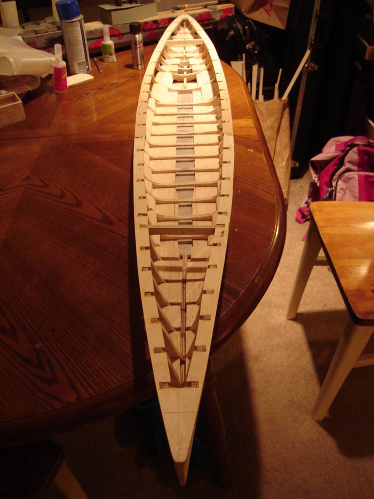
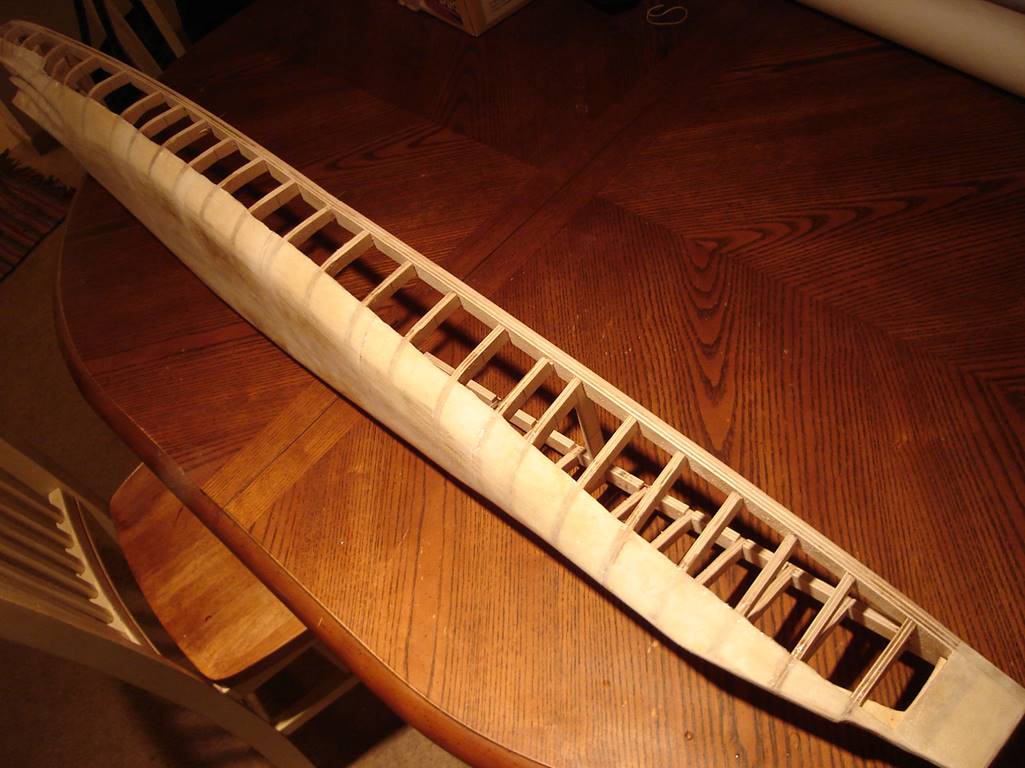
pictures in this article). Wood ships start as a set of plans that are
developed into ribs and decks. The ribs, subdeck, and base board are ¼ inch 5
ply birch plywood. Larger ships like battleships and most battlecruisers are
probably better off using a base board (¼ inch ply wood) so that the water
channeling can be directly cut out, whereas smaller ships can be built upside
down with the subdeck serving as the foundation and the bottom planked with
thin ply wood and fiber glassed. The base board also allows for a very solid
foundation to build up the rest of the ship, and also allows for water
channeling to be incorporated into the build from the early stages. The subdeck
is cut with notches to accept the ribs, it is 5/8 inch in width but I would
usually recommend making it up to 1 inch if space allows in order to obtain a better seal. The deck itself is not installed in
this picture but was made from 1/8 inch thick 5 ply birch plywood. The outer
lip of deck that is attached to the subdeck is generally ¼ inch wide in my
ships. Just like with fiberglass kits, a lot of factors contribute to where
ribs should be placed – the section in the far bow as well as underneath the sidemoutns generally collect more damage, so more ribs can
help keep some bb’s out, some hulls are very curvy and need more ribs to hold
odd shapes and curves, some hull features such as steps and casemates allow for
good areas to put ribs as well. Usually 4 inches apart is about as maximally
spaced as I would recommend placing ribs and the rules dictate that they can be
no closer than 1 inch together. The number of ribs is generally 85% of the
total of the hull minus 2 inches in the bow and 1 in the stern, multiply the
remaining inches by 4 to get the number of ¼ inch ribs. For the Derfflinger I built it with every rib the plan set came
with (so they are relatively evenly spaced) and then cut out a few out so I
would not have too much impenetrable side area. Generally speaking the stern
needs fewer ribs so that is where I ended up cutting some out. Another
challenge of wood hull rib placement is when you want a rib where the plans
don’t exactly have one, in this case you have to extrapolate and make drawings
in between hull lines. If there is doubt it is easiest to make it too big and
sand it back flush with the surrounding ribs and subdeck. The notching of the
subdeck can be done along the inner part or the outer part, placing the notches
towards the outside probably allows for easier workup and sanding and placing
the notches on the inside as I did in this case probably allows for greater
expansional strength (a sunk ship taken directly out of the water tends to
stretch the ship width wise. However by the time it is made up and glued and
epoxied together either way is strong enough.
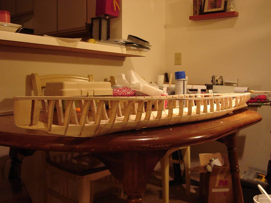
Here is the ship at an angle. The bow of this and many
ships actually angles slightly upward where as the
stern is relatively flat. Ribs should be marked roughly where you think the
water line will go and 1 inch below that mark in order to know where to start
the impenetrable lower portion of the hull. It is a bit tricky to know where
this will be when it actually floats, which is an advantage of starting with a
fiberglass hull that you can simply weigh down to what you think it will battle
at and measure it in a small pool. If someone else has the same or similar
ship, start with where their waterline sits in that ship. I would generally
advise going slightly too deep and being able to build back up if needed rather
than not going deep enough and having to cut or sand a bunch of material out
later. Most of the ribs on this ship are between 3/8 and ½ inch thick, I
wouldn’t for large heavy ships go much thinner than that. Small ships like
destroyers can get away with ¼ inch ribs but don’t expect those to hold up to
fire over time very well. All of the structural wood is ¼ inch 5 ply birch
plywood. The fill in wood is balsa cut to the right size and glued in between
and sanded to shape using the bottom and side of the ribs as a guide. Most
ships can be filled all the way to the bottom of the penetrable area forward of
the bow most turret and also in the extreme stern but to a lesser depending on
where the drive gear will go. The sides of most ships (bulges) should also be
built up to keep water from collecting on a side and causing the ship to roll
over. The width of the balsa in the bulges is a balance between having enough
to matter and leaving enough room for the internal components.
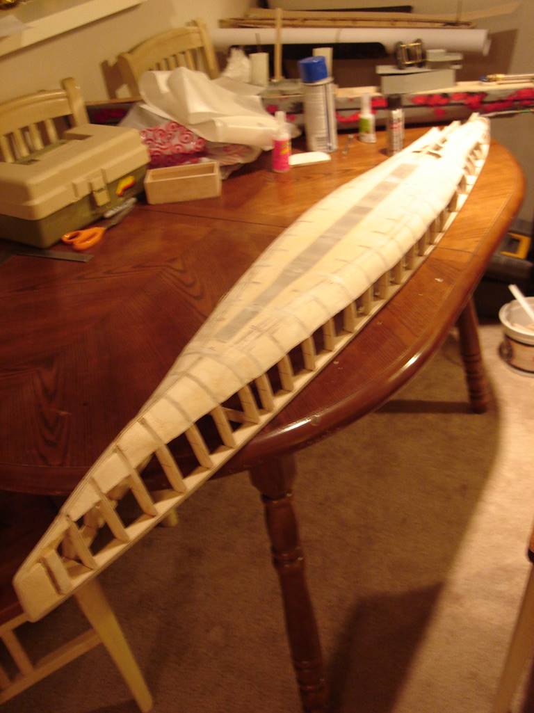
This picture is a bit blurry but I included it any way
because it shows roughly where the base board is and where the balsa blocks
are. Down the middle along the center line is a cut out section that serves as
the lowest place in the ship where the pump will sit and also allow water to
pass freely under the other internal components. Additionally having a lower
section of water channeling directs even small amounts of water to the pump and
improves performance. This ship was built with 3 layers of 5 or 6oz fiber glass
cloth and epoxy covering the bottom of the hull including the water channeling.
This was probably a little too weak and though it never had actual problems I
later cut it out and covered it with 1/32 inch play wood and re-glassed it.
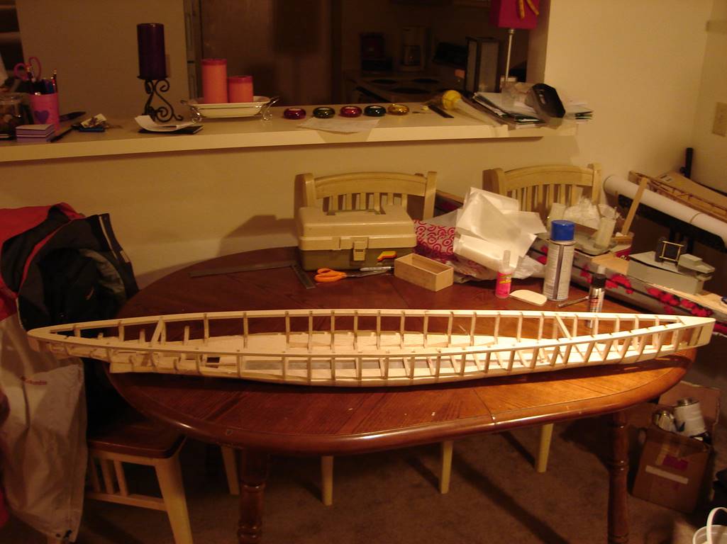
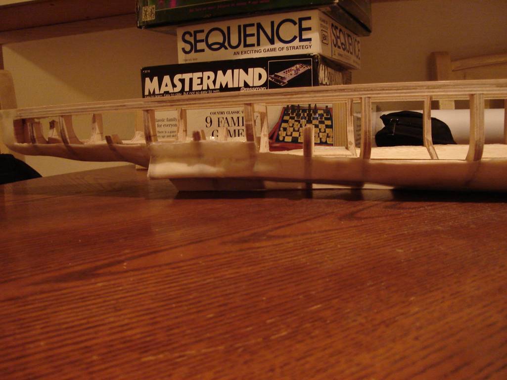
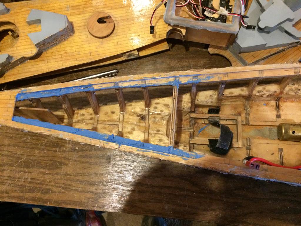
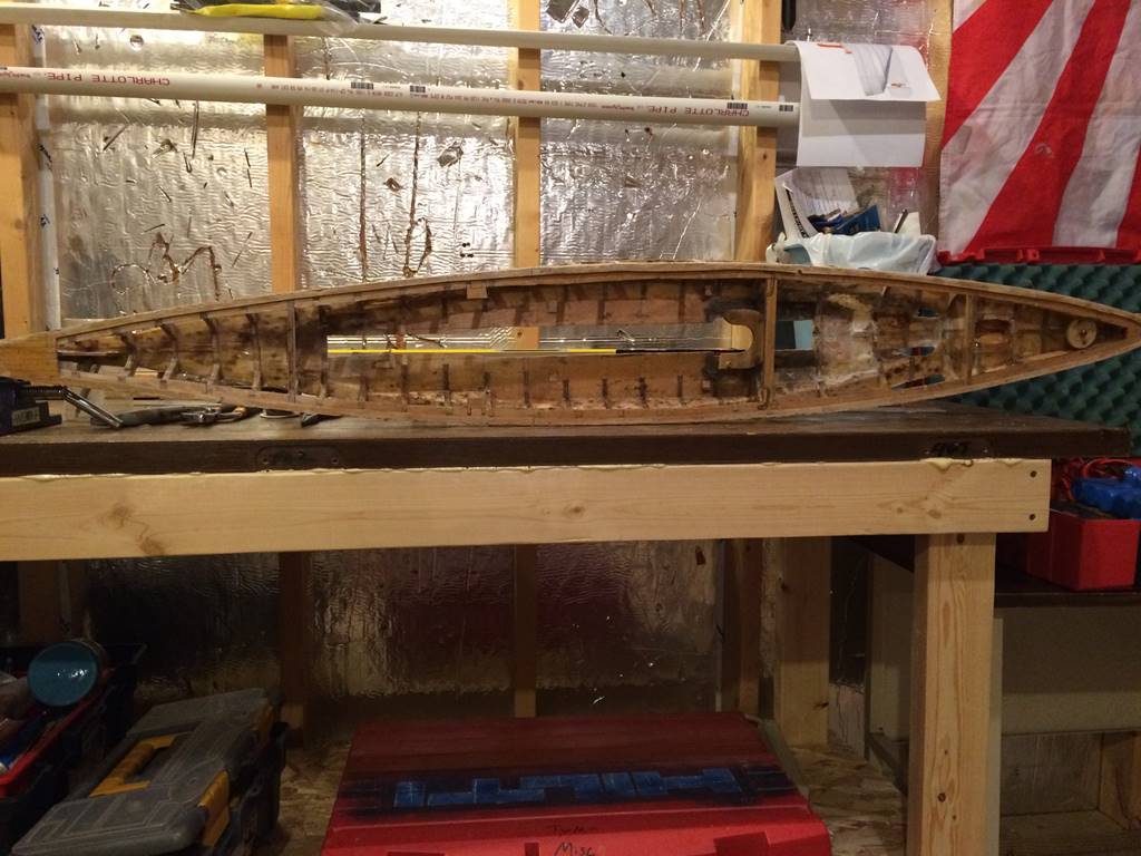
Side profile. You can see where some of the ribs were
already marked by partially cutting and to later be completely removed in the
stern (left). I knew these would have to be removed so I didn’t notch the
subdeck in that area but rather meshed it flush with the subdeck. The bottom
part of the ribs in the center of the ship can be seen above the base board.
The ribs are notched into the baseboard and once everything was glued in place
the excess was trimmed down flush to the baseboard. I leave it in place
initially to get everything flush and structurally sound before cutting them
back. There are only 2 widthwise structural supports that were included in my
original design, one in the bow and another in the stern. This was insufficient
and the ship began to warp slightly over time, subsequently I had to
incorporate in with the subdeck an additional cross beam and later a second
one.
Another view along the side of the ship.
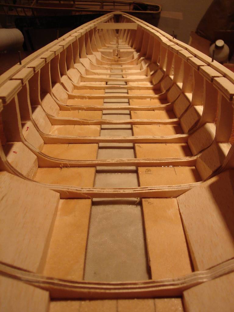
This is a good look down the centerline/water channel
from the inside. The bulges are filled with balsa, probably not necessary to
slope these, it would be fine to leave them square. The base boardhas pencil marks next to the bulge where it is cut in
order to accept the rib, the rib to the center of that has the bottom ¼ inch
cut out of it. Ultimately the ribs are all cut out in the middle of the ship,
to become flush with the base board. Once the sub deck/deck is in place there
is plenty of support and you don’t need to worry about structural compromise.
Another aspect to keep in mind is that if
you notch the subdeck from the inside and the ribs are not wide enough,
there will be a gap that can later be filled in with little ¼ inch plugs.
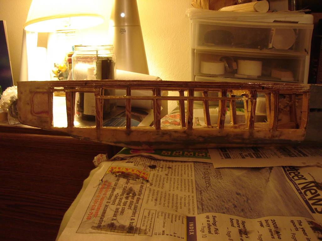
The stern section of the ship. There are a few incomplete ribs that were included to
help shape the bottom of the hull but ultimately needed to be cut out. I didn’t
notch the subdeck where these ribs go but rather meshed them flush with the
subdeck.
When I first built this ship, the armor bulges were
not modeled. They were in the plans and you can see the slight step on
historical pictures of the ship. As an afterthought I went back in and added
them to try to keep some bb’s out of the bow. Here they are seen made from
brass strips, this was too thin and got shredded by incoming fire. I later
replaced them 1/8 inch x ¼ inch aluminum bar that I bent to shape. A similar
one was placed in the stern where a similar hull feature existed on the actual
ship, and thus can be modeled.
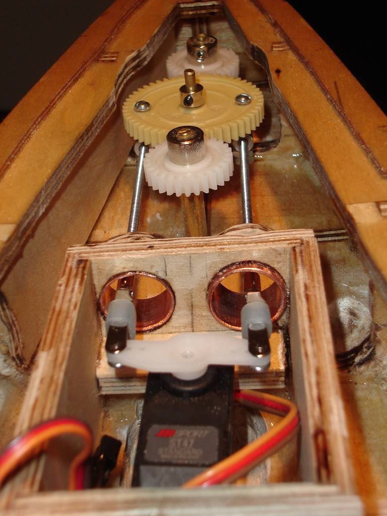
The Derfflinger has two
inline rudders. The stern most is functional while the bow most is but a post.
This was the solution I came up with for turning both rudders simultaneously
and is the solution I have stuck with over time for all subsequent multi rudder
ships. Like most things in this hobby, this is nothing I invented but rather
looked around at what others were doing and made it my own. If there is room in
the stern I will use a large gear glued directly to a servo horn rather than
the linkage. The push arms made from stainless steel threaded rod size 4-40
with linkages. Future versions of this setup in my ships are made by just
taking the rod itself and bending a 90 degree angle into it and feeding that
into the servo horn and the large gear with 4-40 bolts and washers to hold it
in place, less potential for failure and rusty parts in my experience. Also, on
most ships I have moved to water proofed servos without a water tight box.
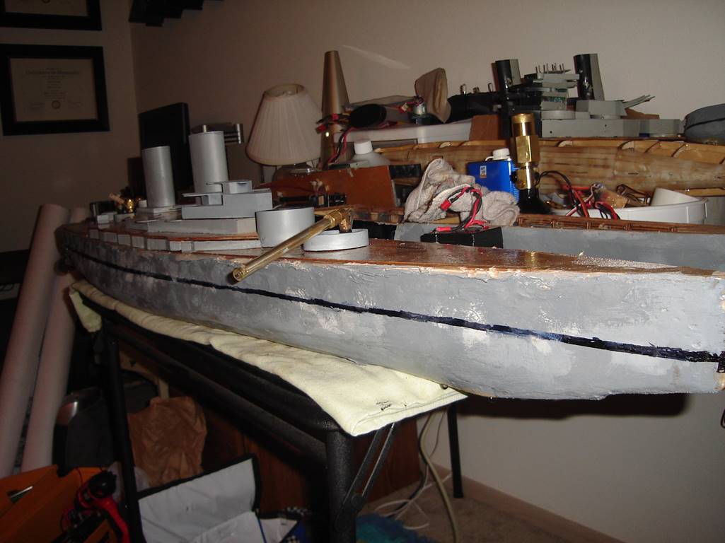
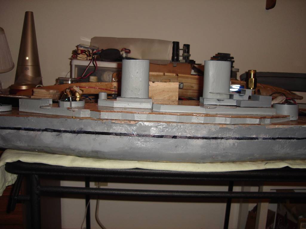
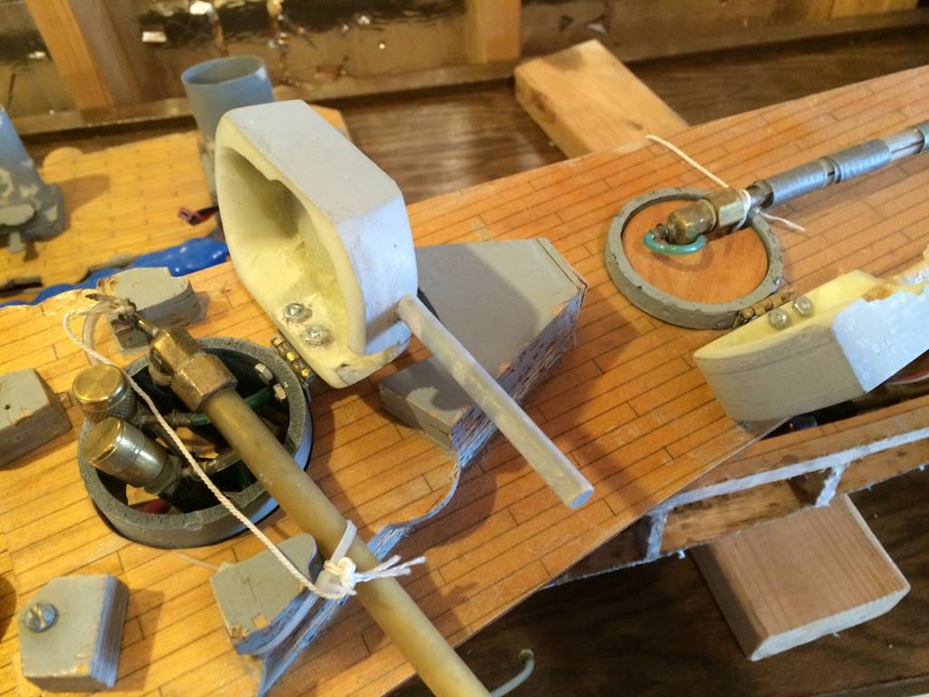
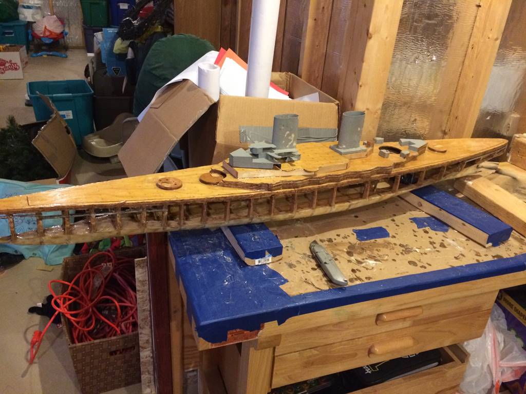
Side profile of the ship. Evidently, I did a lot of work
and battled it before I took another picture. This picture is from the late
fall of 2008. The super structure is ABS plastic. The funnels are custom made
fiberglass ovals that I built over a PVC form. PVC will bend if you heat it in
the oven and originally I had the modified PVC pipes on the ship but it was too
heavy. Saran wrap doesn’t stick with C.A. glue so I wrapped the PVC in plastic
wrap and superglued fiberglass cloth around it, easily removing it when it
cured. Then I added a few more layers of fiberglass with epoxy and sanded it
smooth. It has held up well durability wise but the paint will chip when it is
shot because the fiberglass is so flexible, but it is very light though which
is an important aspect of superstructure design. The center part of the
superstructure’s lower two decks is wood. Mostly I wanted the wood deck look to
it but it could have been made of plastic. The upper parts of the
superstructure are made of 1/8 inch thick ABS plastic sheets which is very
durable and relatively
easy to work with. The turret barbettes are PVC pipe,
they were later replaced with ABS pipe as it takes damage without shattering.
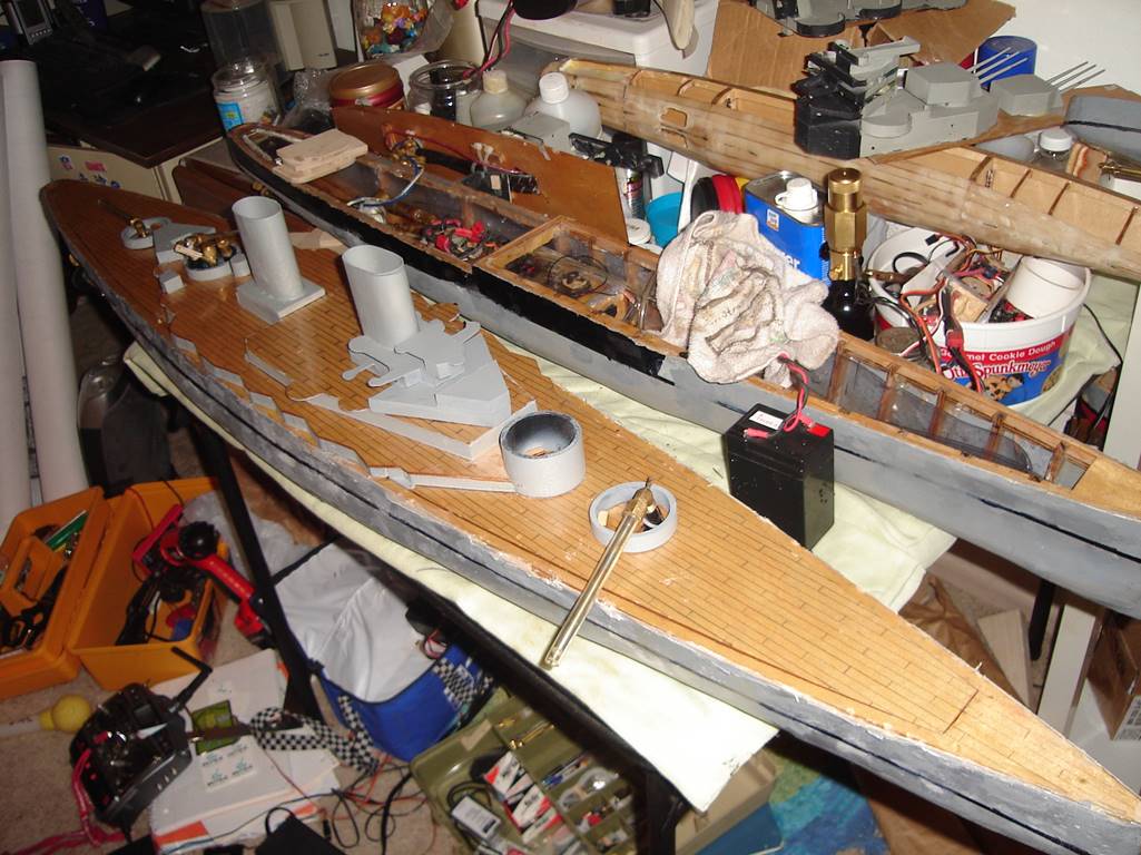
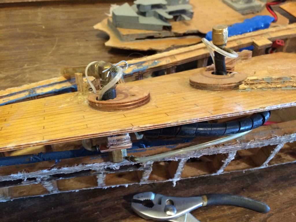
Overhead view of the ship. I made planking lines out
of pencil on the deck before I coated it in epoxy. The gun setup is single
stern gun 50 rounds, 75 round haymaker which is strapped to one of the
superstructure bits in the back part of the ship, and 50 round bow sidemount which was way too long when it was built. It was
constantly hit by passing ships which would bend the barrel and break the
mount, so I ended up settling for less velocity and cutting 1-1.5 inches off
the end. My wood hull USS Minneapolis and FN Mogador are seen in the
background.
Shot down the center line shows an early version of
the gun mount. I still use zip ties heavily in securing guns because they are
very firm but yet removable. Most of my guns now have a piece of custom drilled
plastic block inside the barbette that holds the barrel right next to the
tweaking nut.
Side profile.
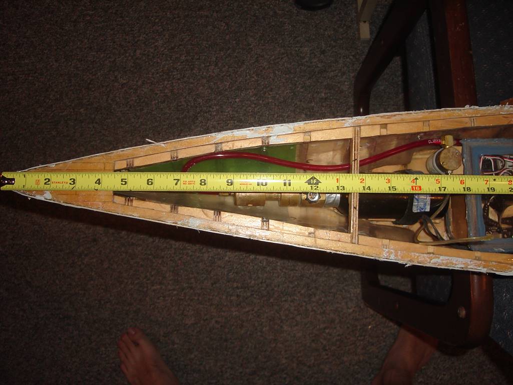
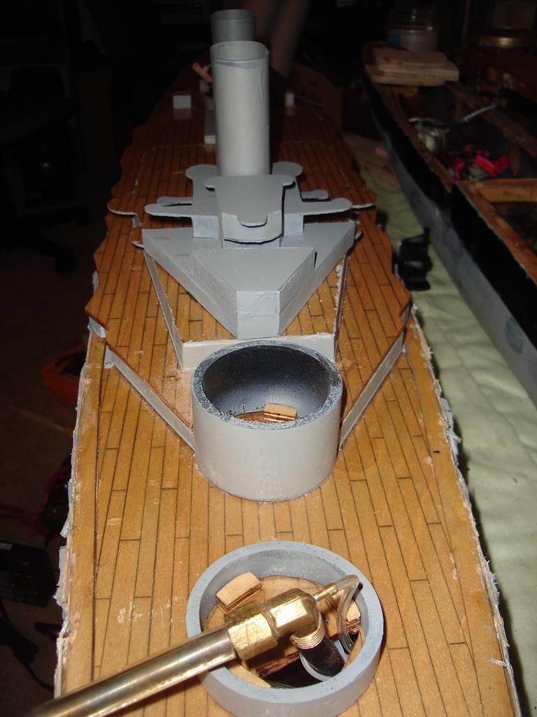
The bow of the ship holds the CO2 bottle. The bow gun
solenoid is zip tied to the radio box. The regulator sits on the raised area in
the bow. The internal armor is plastic beverage bottles cut to fit, very light
but holds up well, and adds a delicious component to the building process.
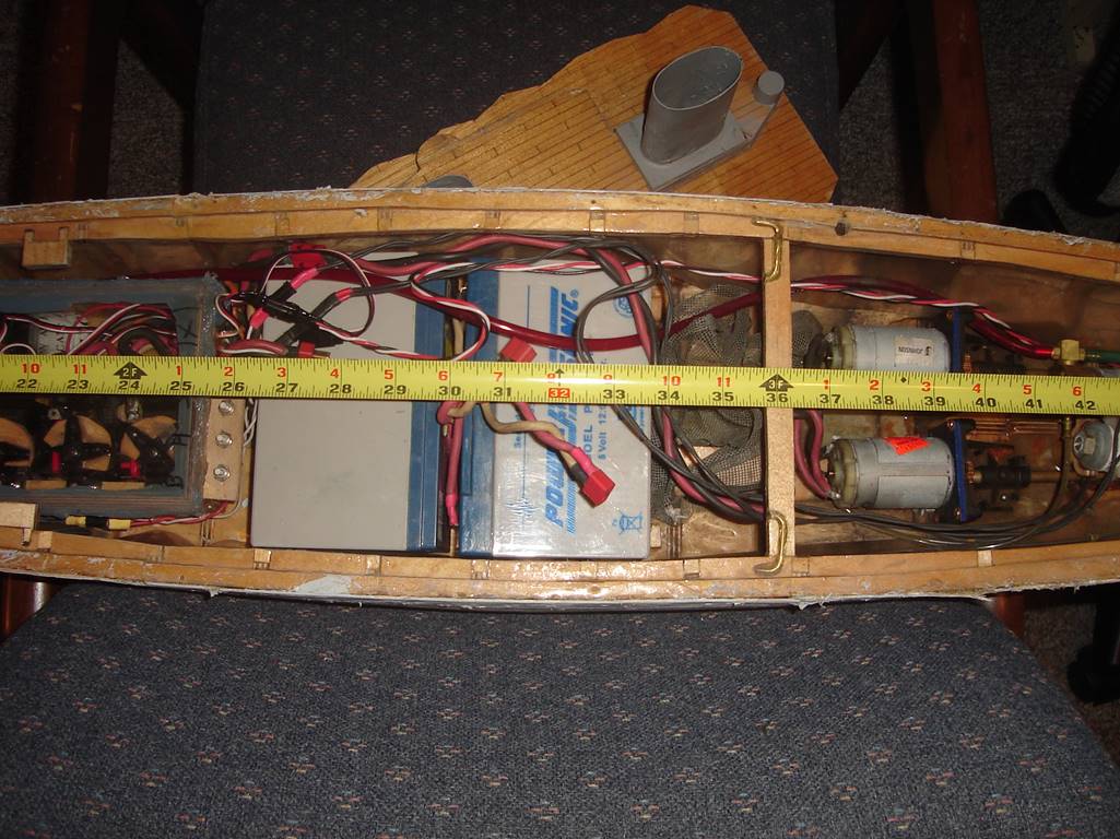
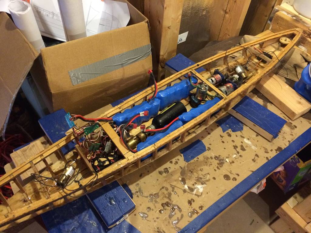
The center of the ship holds the batteries. As built it used two 12 amp hour 6 volt bricks. The radio
box is more towards the bow, on the left of the picture. The pump isn’t in the
picture but the mount for it sits right behind the batteries just forward of
the cross brace. Drive motors are towards the stern, past the cross brace. Gun
solenoids in the far stern in front of the rudder setup. You can see the cross
brace that was added as an afterthought. I embedded bent brass rod and epoxied
it in as a means to add some structural support to the beam, it was a very
early addition to the ship and has held up well over the years of abuse, I’d
probably add a screw in from the side if I did it again. Right next to the
radio box there is another part of the sub deck that was extended to allow for
a deck latching system as well but I didn’t extend it to a full width cross
brace in this iteration, later I did complete the distance and made it a full
width wise support.
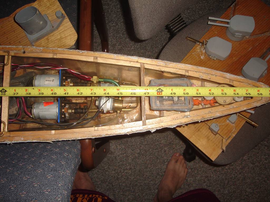
The stern of the ship. Again pictured are the motors,
solenoids, and rudder box and rudder gears.
I like bent magazines that load into the same or an
adjacent turret. This can be a bit of a pain if you try to bend it too sharply
in that it can cause the bb’s not to feed reliably and you can get some jams but
it is very convenient for loading the guns without taking much of the ship
apart.
The stern of the ship has two guns that both load
through the C turret. The Stern sidemount is held in
place with a zip tie attached to nearby superstructure. The stern gun rests on
the barbet and is held in by zip ties as well.
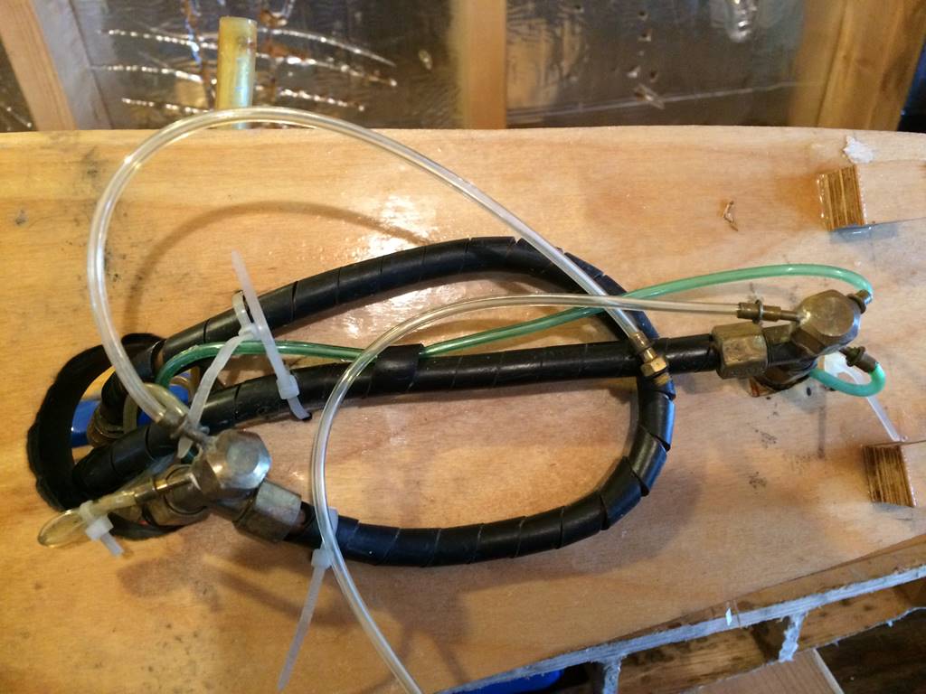
Both the stern gun and the stern sidemount
bend around to load into the super-firing stern seamount C turret. Zip ties are
a great way to hold guns in place that is very adjustable and can be removed
quickly if needed. Plastic spiraled wire wrap protects the gun magazines
internally, if a bb should sneak into the hull and hit an exposed brass
magazine it will deform it and cause jams, magazine protection is a must.
This is a pretty good look at the bow section of water
channeling. It is balsa wood covered with fiberglass and epoxy that initially
wasn’t firm enough to resist all of the incoming bb’s and there are a few that
are imbedded. I removed some of them but there are stains left over. Since then
I did re-fiberglass the top of it to be more resilient. The bottle holder is
also seen as well as the area that is cut out of the bow water channeling to
accept the bottle. With the Velcro strap it stays pretty secure. The blue goop
on the deck is a gasket sealer that was put on in heavy weather at nationals in
2014, it was later removed. I’m not a fan of additional deck sealing material because
most of the time a good latching system keeps enough water out.
This is a picture in the middle of a re-fit which
began in 2015. The bottom fiberglass layer was cut out of the water channeling
to be replaced by thin plywood and epoxied over again.
Again in the 2015 refit phase. The wood sides of the
lower superstructure were completely trashed, I ended
up sanding them flat and placing thin ply wood over the exterior and
re-enforcing the underside significantly with fiberglass and epoxy. It’s
difficult to appreciate without the middle section off but there are 3 sections
of deck that are fairly seamless. The front section holds the two bow most
turrets and the stern section includes the two stern most turrets and the
raised section surrounding the stern sidemount as
well. Both the bow and stern pieces slide into place and lock in with deck
latches. The middle section has seams that are hidden under the lower level of
superstructure. The lowest level of superstructure overlaps the bow section of
deck and tucks under and is held down by the small bits of grey superstructure
that sit forward of the C turret. If you look closely you can see the strips of
aluminum in the bow and stern that serve as very durable stringers for the
armor belts.
As of 2019, this ship hasn’t seen the water since Andy
used it in 2014. A major refit has been slowly ongoing since 2015. I have been
slow to work on it because of interest in other ships but hopefully will come
back to this oldie but goodie someday. I intend to change the internal layout
as picture above but will likely need to move some weight forward to balance it
correctly. Having a relatively empty bow is desirable because it decreases
angular momentum and allows you to turn sharper, so putting in four NiMH 6v 10
amp hour packs will give it more power for the same weight, but also better
weight distribution as it also allows the bottle/regulator to move from the bow
to amidships. This also makes pond side maintenance easier as the bow and stern
sections of deck will probably be able to stay in place for most of the battle
day, only needing to remove the middle section which is between the cross
braces. You can see I ended up completing the cross brace
that sits more to the bow, above where the radio box will sit.
One of the main take home points from this article is
that not only because of mistakes, but also because of upgrades in technology
and technique, you need to be willing and able to put time and energy into a
ship to keep it battling in top form. I was able to win NATS most feared in
2009 but have yet to consider the project complete.