Inside the HMS Warspite
Class 5 Battleship 5.5
Built by
The Warspite has served me well since in construction in 2003. Well, the first two years where kind of rough as I had not build it very well. But after two major and two minor refits she has become a very good ship, helping me win Most Fear and Best of Class awards at Regional’s and NATS.
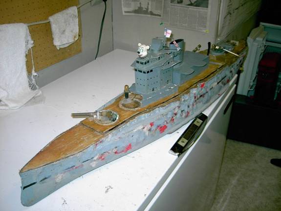
A Best of Scale ship she is not, I’m not big on pretty things. You can see in the picture that there are several pieces missing after a year of battling. Two barbets, three turrets, the aft superstructure and the main mast have all been broken off. I have all of my guns filled through the deck; I think it is a lot easier this way. The big polar bear head is connected to an old servo and spins when my pump is on. This is a great help reminding me to turn my pump on in the heat of battle. Once and a while it gets unplugged and is very unnerving not seeing it spin. The bow sidemount is angled off the bow 80 deg and down 10-15 deg. This hits about 7” from the side of my ship. The gun is held in place by a zip strip. It would be better to have a more solid mount for this gun. It does get run into and moved around during battle. The bow deck is one large piece that is held in place by screws glued through the deck and large finger nuts. A hold over from is original construction. A better system would have slides or latches, something that does not get dropped in the grass like these nuts do.
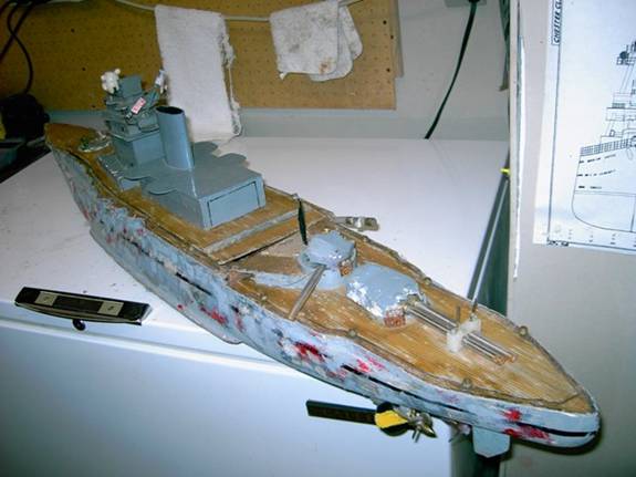
The stern deck is also held on by six screws and nuts. There is a gasket under the deck to help keep water out. Each of the barbets are sealed to keep any ships trying to prop wash my under. The stern guns are held in place by a plastic block. The screws are set up to be adjustable to change ranges. The stern guns hit the water 4”-5” behind the ship. The stern sidemount (Haymaker) is angled 85 deg of center and 20 deg down. If the side of my ship is touching the side of another ship I will be hitting them with bellows. The pump hose is very long so I can get the pump out of the housing as you’ll see latter.
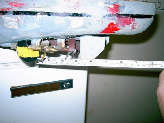
Here you can see the prop and rudder locations. The inner props are powered in both directions while the outer shafts are powered in reverse only. The super reverse gets the Warspite moving very quickly from a stop to get the haymaker on target or helps me stop keeping it on target, it made the ship go from pretty good to really good. The inner props are 3 blade 2” cast props I sanded down to a little under 1 ¾”. The outer props are 4 blade 1 ¼” 25 deg pitch props. This one broke and was replaced with a three bladed prop.
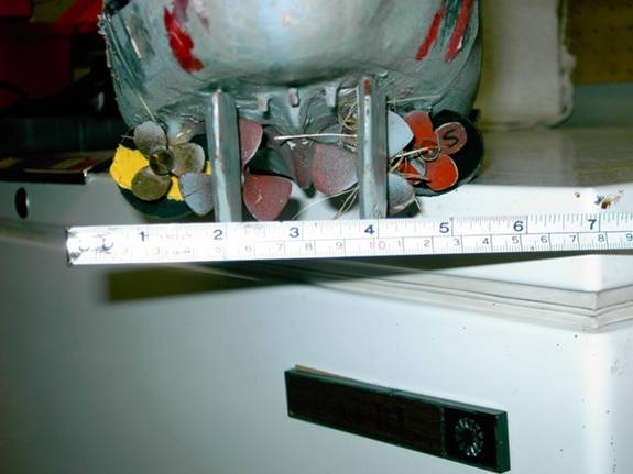
Here is the stern of the ship. There are little screws sticking out of the hull that stop the rudders, since I did not have adjustable end points on my radio.
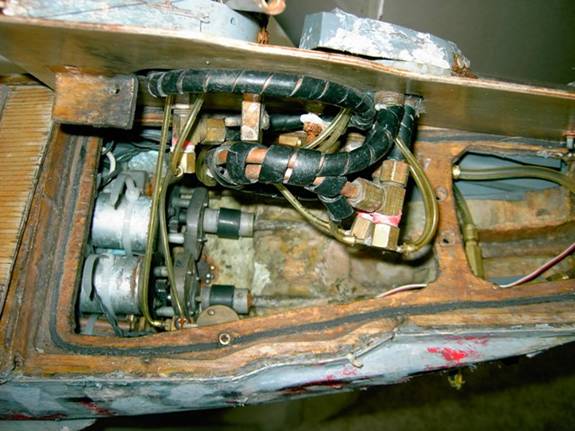
This is a view inside the stern with the deck almost on. It is very cramped inside. You can see two of the solenoids mounted upside down and to the sub deck.
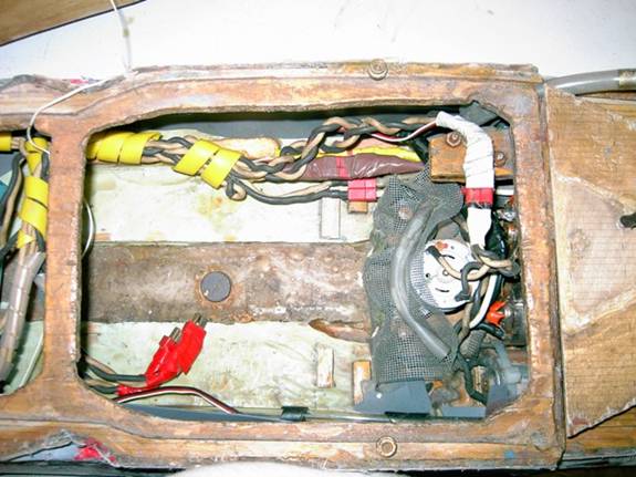
At the right is my water proofed rudder servo. In 2005 I made a water tight box around this set up. I failed to put any o-rings in the rudder post so it leaked. Wednesday of NATS I ripped the front wall off and it work out in the open. There is a channel into the balsa water channeling that helps keep the water away from the servo. The top gear is 44 tooth the metal gears are 22 tooth. It would be better to put the set screw side of the gears up so it is easier to take them on and off. But I did not have the room for that. I think there is room for a water tight box right by the cross brace, it’s on my long range refit list. The stern guns loop around and are feed through the turret they shoot out of. You can see a check valve that was added to the stern guns. It made them a lot easier to tweak.
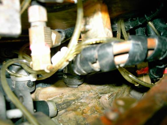
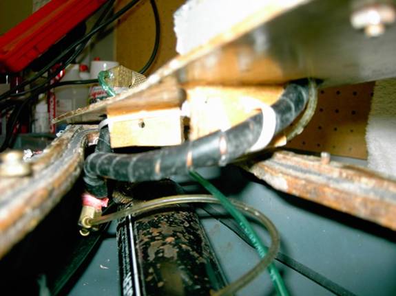
The haymaker also loops around and is fed in the same turret it is fired from. The drive motors and older style Battler’s Connection gear boxes are on the left. I do not like these gear boxes as you need to take the motor completely out to change gears. The couplings, also from BC, are very strong and work very well. The reverse motors are mounted lower and to each side of the main drive motors. The haymaker solenoid is at the bottom of the photo The accumulation tank feeding it also feeds to both stern guns. All of the barbed fittings have a hose clamp on them. I have not had one of these blow off. I have had the 1/8” hose blow. The water channeling back here is as deep as I could make it up to the bottom of the windows. I had to cut little pockets out to get the guns and solenoids in place.
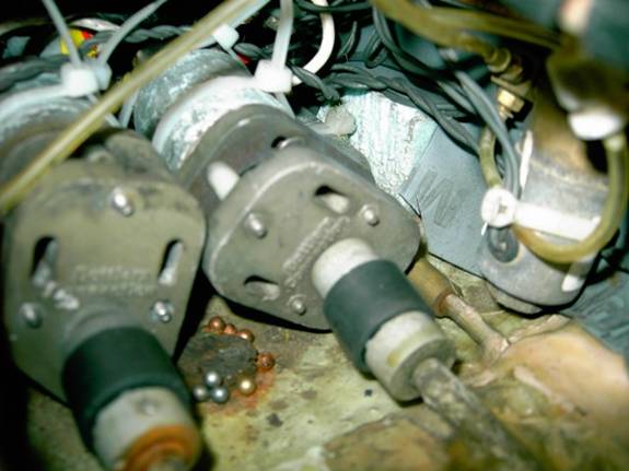
A close up of the drive motors. You can just see the reverse motor and coupling on the right. These motors are direct drive. I have a little magnet glued to the hull to collect bbs.
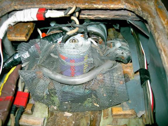
On the right you can see one of the reverse motors. The little piece of wood at the top left holds the test switches for the stern guns. The Deans Ultra connectors are used for each connection; these are the only connectors I use. They are easy to solder together, take apart and never corrode. I have used electrical tape to color code the connections. Surprisingly the tape has not come apart after all the time in the water. I have used 14 gage wires for all my wiring. I could have used 18 or 20 gage wire and Deans micro connectors for the guns. The stinger motor on the pump will pump out almost 2 gallons a min. I have built a screen house around the pump that does a great job keeping all the bbs, balsa and other junk away from the pump. The big flap of screen in the front is held in place by a small piece of hose and some Velcro. It opens to let the pump slide out. The hose at the right is the CO2 line to the stern. Tied to it is the rudder wire.
This is where the batteries sit. I use two Eagle Pitcher 12.7 amp hour 6 volt batteries. The deans connectors in the center plug into the batteries. The small blocks on the water channeling hold the batteries in place. The small magnet on the hull collects bbs from the bow. The water channeling is ¼” deep at the outside of the hull and slopes to the main channel to a little over 1/8” thick.
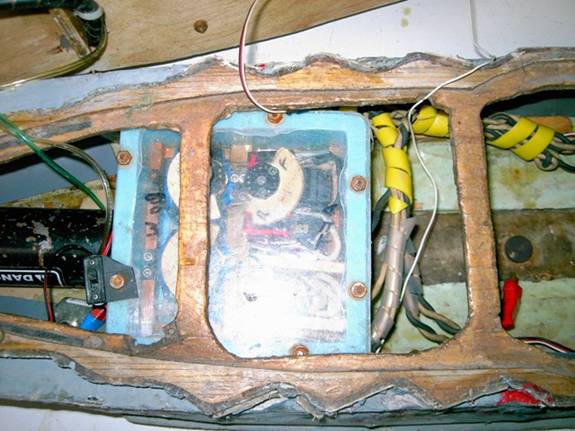
The radio box is cast plastic from BC, but they no longer make it. I have marked the lid with bow and aft so I put it on the right way, of course the last time I must have flipped it upside down. The servo on the top right is the throttle with a standard two switch (MAG) set up. There is one reverse only switch glued on the normal reverse switch. The top left servo is for the stern guns and haymaker. The bottom left servo is for the bow sidemount and the pump. The pump uses a large push button that is hidden by the flash glare. I radio is powered with a separate receiver battery; the on/off switch is on the left side of the box. It used to be screwed on the deck but it had to move when the radio box moved farther up front. The lid is held in place with eight bolts and nuts. Not something that is needed but may help keep the lid on if you sank in deep water.
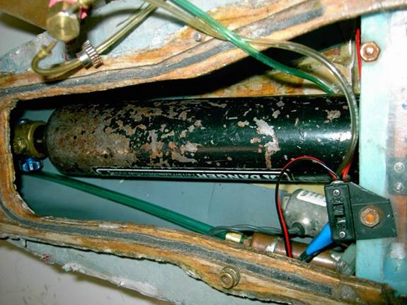
Here is the 9oz CO2 bottle with the regulator tucked up front. A 7oz bottle would work and if you are careful with your air a 3.5oz bottle will have just enough. You can see the solenoid for the bow sidemount and its accumulation tank. The interior armor is shower pan liner that you can get at Home Depot or Lowes. In this ship it just lays in place, it should really be glued in to keep it from falling down. At the top left you can see an old gear on the gun hose. This hose goes to the back of the magazine. It was an experiment to see if cutting down the air to the mag would let you tweak harder. It kind of worked but not enough that I did it on all my guns.
Here you can see how the bow sidemount sneaks in under the sub deck and alongside the bottle. The fed end is bent up into the B turret. The guns are BC guns that I added a breach by-pass to. This gave me a little more power and now makes a lot bigger splash.
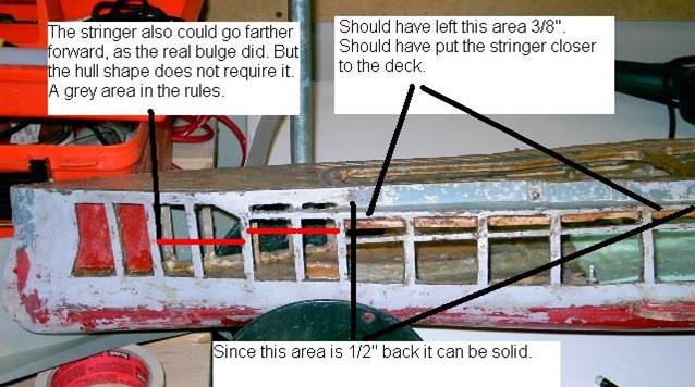
I bought this hull after it was cut out. There are several things that I would have done different. When the torpedo bulge was added, to the real ship, it extend pretty far forward. The rules say if there was a bulge you can have a stringer, but this fiberglass hull does not have a big enough “bump” in it to make you “Need” a stringer to sheet. With this grey area in the rules you could put a stringer farther forward, but this hull was not cut that way.
When the hull steps back ½” that area can be solid and the 3/8” deck drops down. This hull was not originally cut that way so I added some wood to make most of the lower deck 3/8”. If I had it to do over again I’d leave the fiberglass in place and move the stringer so the area between the deck and stringer was just bigger then a bb.
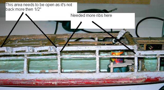
The casement area steps back to with-in ½” of the edge of the hull and the 3/8” deck moves back up. The lower deck is 1/8” taken from the 3/8” main deck. The little slots end up being just bigger then a bb. I saw one QE with the casement barrels modeled with 1/8” brass rods. The barrels were placed right over the holes in the hulls. This kept almost all the bbs out of the slots.
The area where the casements end before the deck steps down should have 3 or 4 ribs in it. This area gets hit with a lot of stern guns.
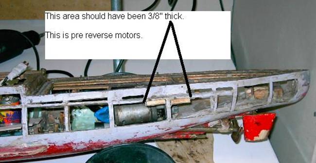
In the stern the hull again steps back more then ½” from the edge of the hull. The 3/8” deck again drops down. Again I had to add some wood to make this solid again. This extra solid area works out well because you take a lot of sidemounts shoots under your stern sidemount.
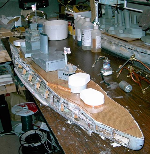
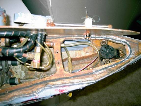
The winter of 2009 & 2010 the deck and sub deck of the Warspite was replaced. The old one was never sealed very well and was starting to fall apart. It came out very easily. The new deck was installed with marine epoxy and sealed. This photo shows the ship with the new deck finished. I also changed the way the deck was held down. I now have slides for both the upper and lower deck. NO MORE SCREWS! The top deck is cut right by the stern section of super structure. This helps hold the lower deck inplace.
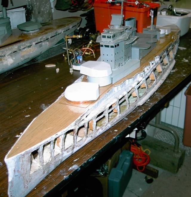
The bow view.
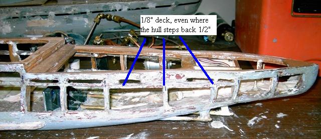
Earlier in the article I had some photos of the casements in the ship. After learning more about them over the years I have changed my opinion on how they should be done. The 3/8” deck should not jump up and down based on the ½” step back of the hull. As in the photo above if the main 3/8” deck moved down this would be the “sink deck”. On Warspite this deck is under water most of the time the ship is moving. Pretty easy to be sunk like that.
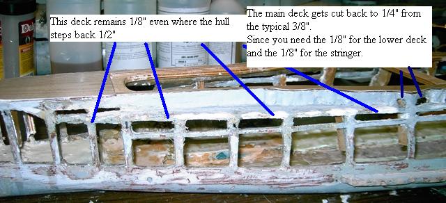
The same thought applies to the bow of the ship. It’s not in the photo very well but at the right you can see the area where there are two decks and a stringer for the bulge. Since you can’t have two stringer you have to split up the main decks 3/8” into ¼” and 1/8” for the main and lower decks.