Inside the USS Minneapolis
A Class 3 Heavy Cruiser with 3
Built by Bob Hoernemann
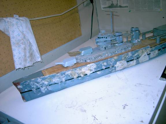
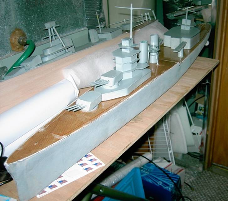
This sheeting has been through one year of battling and has been patched up a lot. The front part (grey) of the main deck is glued in place and the rest of the main level (wood) slides under the front part holding it down.
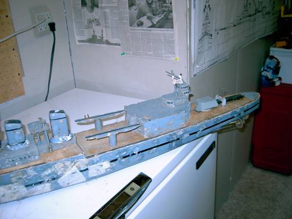
Here is the back half of the ship, not as many holes in the sheeting. The lower deck is held in place by to bolts and nuts just stern of the hanger. If I had it to do over again I would slide the lower deck under a glued in section at the stern and use the turning aircraft catapults to latch the deck in place.
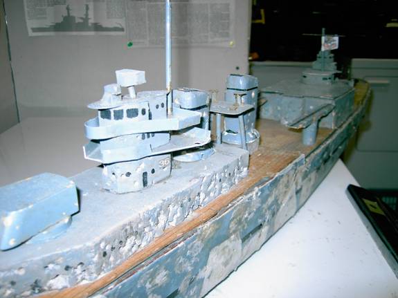
A close up of the superstructure. This is the original Swampy foam (1998) and has seen many battles and many bb holes. It’s light weight but not close to bb proof.
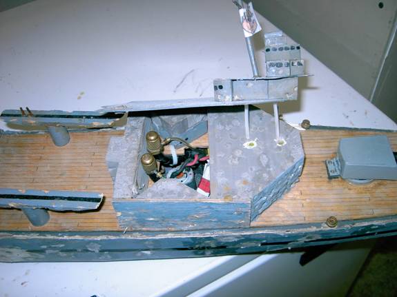
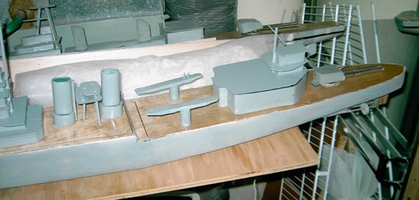
My favorite part of the ship. The hanger deck lifts off to reveal the magazine feed points. Also under there is the pump. This allows me to reload during campaign very quickly. Easy reloading is a must in all cruisers. You can see the hinge at the back of the stern turret. I like to hold my turrets on with hinges like this.
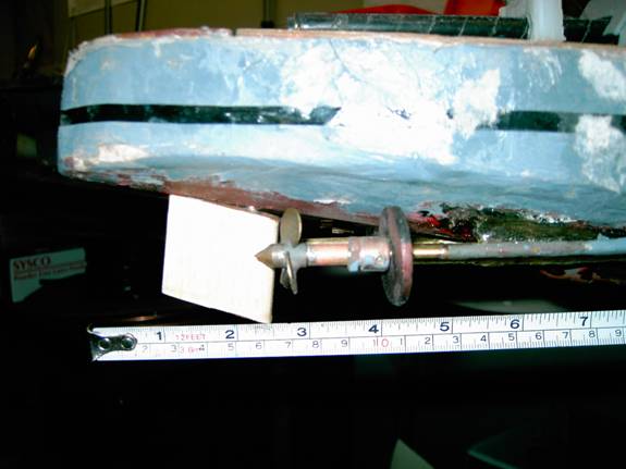
Here are the prop and rudder locations. I have gone through a lot of prop sizes, locations, rudder styles and locations. This is the same set up used by Pat Clarke and gives my Mpls a great turning radius for a cruiser. I use 1 ¼” three blade 25 deg pitch props from Battler’s Connection. The drag disk on the right is used to set my speed since I don’t have a gear box. The shafts are very level and I can back up quickly for a long distance without sinking myself.
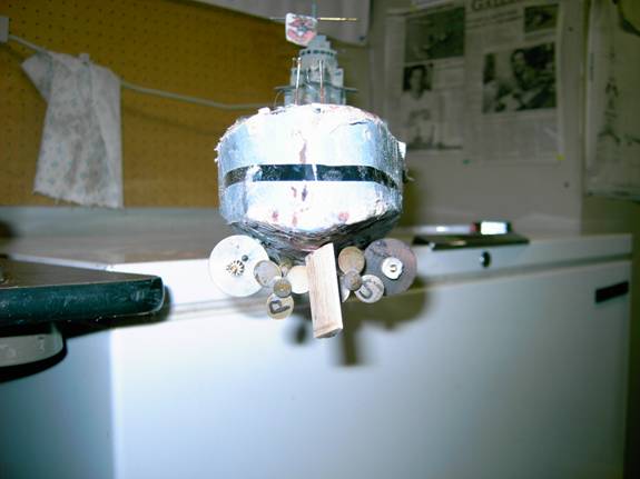
A stern “under water” view. I label my props so I don’t get them mixed up when I take them off.
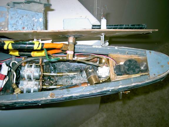
The winter refit in 2007 added a rudder box to the ship for the first time. With the rest of the drive system overhaul I was able to find room for it back there. I have a 44 tooth gear glued on to the servo horn and a 28 tooth gear on the shaft. I use an o-ring and compression fitting to keep water from coming into the box through the rudder post. Just forward of the box are the solenoids with accumulation tanks and check valves. The main hose from the bottle is hidden at the left of the photo. Right next to the motors you can see were the hose is split to the two check valves. The black, yellow and orange wrap is protection from bb dings for the gun magazines. You can see the up feeds for the guns are very short. I have a bracket on deck to hold the barrels in place. It has adjustable elevation screws and a place to put my gun pins when I am on the water. I have never had gear boxes in this ship. Oddly enough it has always been at speed with only direct drive. The first year or two I had a couple of the plastic dog bones break but have had good luck with them since I started to leave a little “play” for them in the U-joints. They should be able to wiggle just a little in there. As you can see everything is very tight back here. The lower deck is held in place by two screws glued into the deck and two nuts twisted on them.
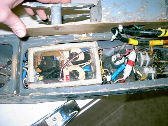
The pump sits right behind the motors and has a little housing around it. There is screen from the housing to the hull so no bbs, weeds or other gunk can get to the pump inlet. If anything does get by that screen there is another screen around the pump and one more screen over the inlet hole. The radio box has three servos and a receiver (bottom left) in it. The servo at the top left is the gun switch. The bottom right servo is for the pump and lights. The top right servo is for the throttle. All the wires into the box are epoxied into place. The antenna, rudder servo and battery wires are cut in a little notch in the top rim of the box and siliconed in. I have color coded the Deans Connectors with tape so I can easily see where each one goes. Colored heat shrink would be better for this.
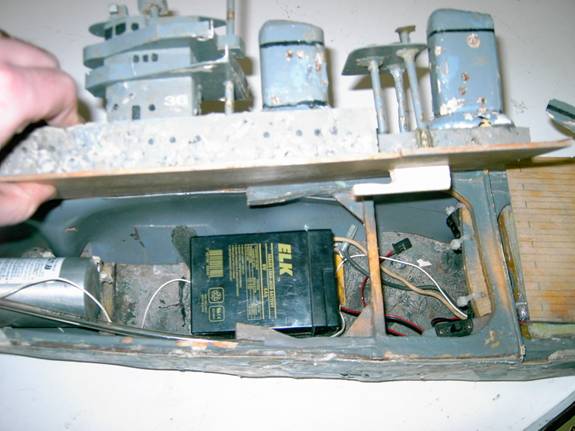
The top deck is held inplace by the hook and cross brace in the middle of the photo. There are two test switches right at the step of the deck for the guns. You can just see them at the right. In the bottom right of the hull I have my radio on/off switch. I still run the receiver off of a separate battery. The main battery is a 5 amp hour 6 volt, a little small compared to some other ships of the same class. I have seen others run a 7 amp hour battery. There is a lot of room up front.
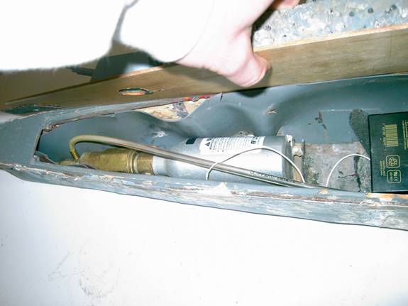
Here you can see the 3.5oz bottle and standard regulator. I can get two sorties, 100 bbs, (not quite 3 sorties) with one tank of gas. I use shower pan liner for my interior armor. You can see the front slide at the top left of the photo. This ship started out with a bow and stern gun. You can see the hole in the deck where the bow gun was. After my first NATS I came home and put in to stern guns. The first thing I learned at NATS was that bow guns are hard to aim.
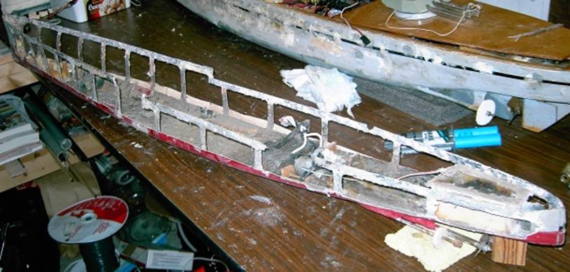
The winter of 2009 & 2010 I replaced the deck. It was old and was never sealed very well. This caused a lot of leaking from the stern deck. The photo above shows the ship without old the old deck. Most of it pulled off easily in a couple spots the old fiberglass came with the wood. I sanded down the rest of the glass and installed the new deck and subdeck.
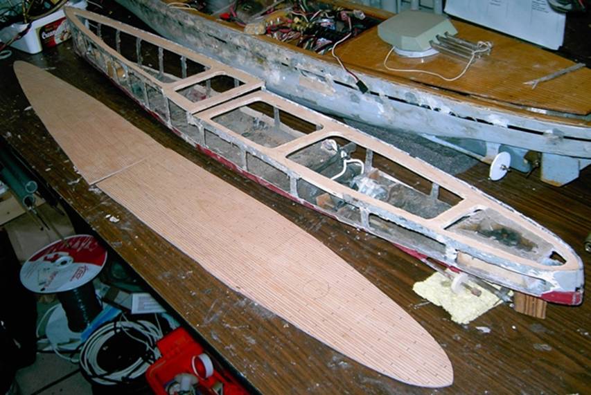
This photo shows the new deck and subdeck before I glued them on. I used a marine epoxy to hold them in place. As I noted earlier in this article if I had it to do over I’d have slides instead of the nuts holding the stern deck in place. There will be two sets of slides at each of the cross braces in the stern section. The bow section will have a copy of the old system.
The new deck is now in placed and sealed. I even made new super structure pieces.
The stern of the ship.
Since this article was first written I have gone to 10 amp hour NiMH batteries. I have also made a new smaller radio box. The other one was not Leaking but the wiring was starting to corrode. A year ago I put in new guns, the PPB Mark 7 style. They are still installed the same way. With the new deck I made the pump outlet hose shorter and pointed it straight up.