- Adding Push Buttons -
Adding push buttons to a radio
Some people prefer moving a transmitter stick to fire
the guns. I prefer push buttons. I have the older style Spektrum DX6 which
requires only a relatively simple wiring modification. Regardless, there will
be some structural modifications as well to accommodate the button. Various
types of buttons could be used, the ones I use are convenient in that they have
a circle aperture and they are threaded so you can just screw a nut on to lock
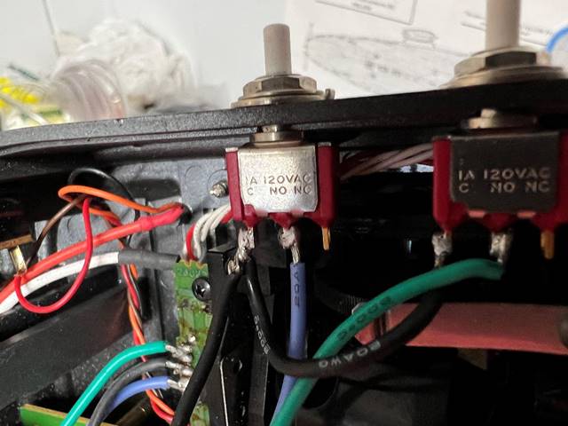
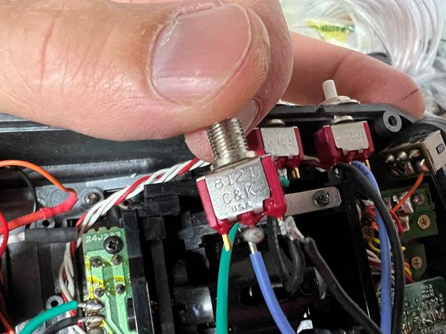
them into place. The switch is C&K 8121SHZGE – 1a, 120VAC, 28VDC. Amp
rating requirement is very low for this application, you will want a “momentary”
switch, which is one that returns to baseline/neutral after you let it go. You
could get a two pole switch that is “normally open” as well.
The first modification I usually make to my
transmitters is to change the ratchet apparatus from the left vertical axis
stick and on to the right vertical axis stick. This will force the boat to
“zero” throttle if you don’t touch it or just let the transmitter go rather,
which to me is preferred to having it drive off if you hand the transmitter to
someone else who doesn’t know your ship or if you set it down briefly and bump
the throttle stick. This also allows me to have a gun stick position on the
right gimbal that is a little more out of the way (ratchet is pushed up and
left there as this is an open ½ channel for most of my ships). One could just
cut the stick off as well. Some of my ships have a spring on both gimbals as
well. Switching the spring on this model is a little tricky just because of the
small space you have to operate unless you take the gimbal out more but it is
do-able with good tools.
I typically drill holes in the side of the plastic of
the transmitter to accept the buttons but ultimately the placement is up to the
user as long as there is space internally. This particular switch has a ¼ inch
diameter circular stem. Be sure to use a firm material for backing when you
drill so the drill bit doesn’t slip through rapidly and damage the internals. I
usually use a piece of ¼ inch ply wood that I squeeze laterally against the
internal side wall as I drill. The plastic in most of these really cuts fast
and grabs a bunch once the hole gets started, so controlling the drill bit can
be difficult. Typically, the holes I drill end up around 1 inch apart but this
can be done differently to preference as long as there is internal room. The
transmitter in the picture below is actually a bit off in regards to the space
between the buttons being quite unintentionally unevenly spaced, but it really
doesn’t matter that much. I would advise not placing them too close to each other
though so you have a harder time accidentally pushing two buttons at once or
pushing the wrong button accidentally, but don’t place them too far apart as it
is easiest in my opinion to feel for the switch and keep your eyes on the water
and you don’t want to have to look down to find the buttons. I like having the
buttons up higher on the radio but I have to carefully Dremel out some of the
gimbal mount plastic to get them to fit. If you don’t mind them on the lower
part of the transmitter, they will fit a little easier. You can also take the
gimbal out and put a piece of plastic or wood in its place with the buttons
mounted on that, but that requires much more modification, and the thumb is a
slower digit than a finger. Additionally, it should be noted that this
modification is easier if you leave the potentiometer in place as you don’t
have to add diodes to take the place of the potentiometer. Without some
mechanism to maintain a neutral zeroed position when there is no input, the
signal from the buttons will confuse the computer and you will have at best a
full swing and hold in one direction when you push the button and release, and
a full swing and hold in the opposite direction when you push the other. Also,
it can be useful for setting up the endpoints if you heave the ability to use
the stick to partially throw the signal, as buttons will only transmit a full
throw.
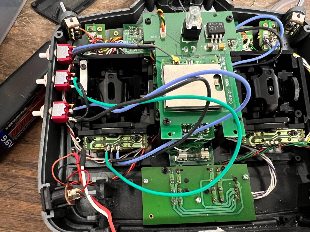
The actual wiring part is fairly straight forward. The
common (C) pole (black wire) goes to the center pin right at the potentiometer
and the normally open (NO) pole of the switch goes to either side of it (green
and blue wires in this picture). You can run a wire from each switch all the way
to the connection point but it is easier and quicker to just run the switches
together with the common in parallel. In this example the top button goes to
the up and down axis and the bottom two go to the side to side axis. Since this
ship required 3 buttons (3 guns), I didn’t bother adding a 4th
switch, as such one of the vertical directions will be essentially an open 1/2
channel. Most ships in our hobby will not require 4 independent firing options.
You have to be very careful not to full on melt the transmitter/potentiometer
components when you solder, it doesn’t take much heat on these tiny
electronics. The switches themselves are very robust and can be over cooked a
bit and still function. I like to leave a little excess wire so things can be
manipulated easier but the one pictured probably has too much extra wire. The
wire in this example was 20 AWG, 22 AWG or smaller would be plenty as very
little current actually runs through this.
When everything
is settled, I tuck in the wires and screw the back on again. Notably this
location of switches requires a little carving out of the plastic transmitter
back where the buttons sit into the mesh of the back/front plastic as well.