
- Ribs -
“Ribs” are vertical structural elements with their
outer edge continuous with the outer edge of the ship. In classic ship construction,
the form of the ship was a keel laid down adjoined with ribs on the bottom
which then adjoined to an upper deck rim to which that skeleton like structure was
subsequently covered with some form of outer layer. In wooden ships these were
flexible planks. In steel ships this would be plates of steel.
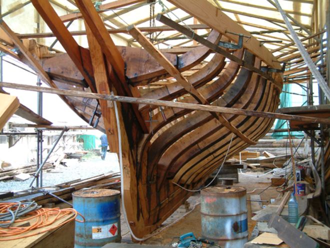
In our hobby, ribs actually serve a very similar
purpose of forming the rigid impenetrable structure of the ship, to later be covered
with the penetrable balsa wood. In the early days of the hobby, ships were
primarily made from wood cut from hull line drawings. Subsequent development of
fiberglass hulls led to greater flexibility and customization of where “ribs”
would be inferred after the penetrable windows were cut out of the side of the hull.
More recent trends have lead to 3D printed ships which
also has some amount of customization as to the placement of the impenetrable
ribs but are more so part of initial design decisions more similar to wood
hulls in actuality. Regardless of material, 15% of the side of the ship may be impenetrable,
typically allocated with 2 inches in the bow and 1 inch in the stern of solid
material which is the maximum allowed per rues, with the rest allocated to ribs.
The functionality of ribs themselves I would argue
have two main purposes. Clearly the structural integrity of the ship needs to
be maintained, and there must be a surface for attaching the balsa hull skinn. We abuse our models and the structure needs to be
robust. One can also argue however that competitive optimization can be
obtained by using the placement of ribs (ie rib
density) as a defensive advantage. Placing more ribs where you anticipate being
shot more should block incoming bbs to a higher
extent.
In general, I would suggest that the places that should
have higher rib densities include: The bow of the ship commonly sticks further
out of the water and has more vertical targetable area, which can be mitigated
by placing more impenetrable ribs in that section. Opposed to that, the stern
should require fewer ribs and lesser protection because it typically has the
lowest vertical targetable area as it slopes upwards to allow room for
props/rudders. Additionally, if you examine where most ships accumulate damage,
the side of the ship within 4-6 inches of a sidemount are typically worth
adding protection since return fire will be focused in this area. Furthermore, from
an advanced and nuanced perspective, various hull features like bulges,
knuckles, and casemates may dictate the utility of adding a rib in a location
that otherwise minimizes penetrable openings in areas of the ship.
There are limitations on selectively placing ribs with
the intent of damage blocking in addition to the rules limiting placement
within 1 inch of each other. Firstly, I would suggest 1/4 inch
wide ribs ubiquitously. Wider ribs (up to 3/8 inch is allowed) will necessarily
lead to placement of fewer ribs and larger gaps between ribs. I would advise
against 1/8 inch wide ribs as a BB is
much more likely to roll off the edge of the rib causing damage that otherwise
may have been blocked and the smaller ribs are also much more susceptible to
becoming damaged themselves since they have less material. Secondly, larger
areas without many ribs make for very flimsy outer balsa which is more susceptible
to taking ram damage and having sections blown out by incoming fire. I would
generally suggest a maximum distance between ribs of 4 inches. Thirdly, the
more curvature there is in the actual ship (more space between hull lines), the
more structural support may be needed to maintain that curvature and thus may
require more ribs. And finally, depending on the type of hull you are dealing with
and the sent of plans you are using (wood hull or 3D design), you may have
limited source material for placing ribs where you actually want them to go,
which can with experience be mitigated by “drawing” your own ribs between where
you have actual hull line data points.
Various examples follow:
The IJN Hyuga is pictured
during a refit. This is a wood hull built with uniformly spaced ribs
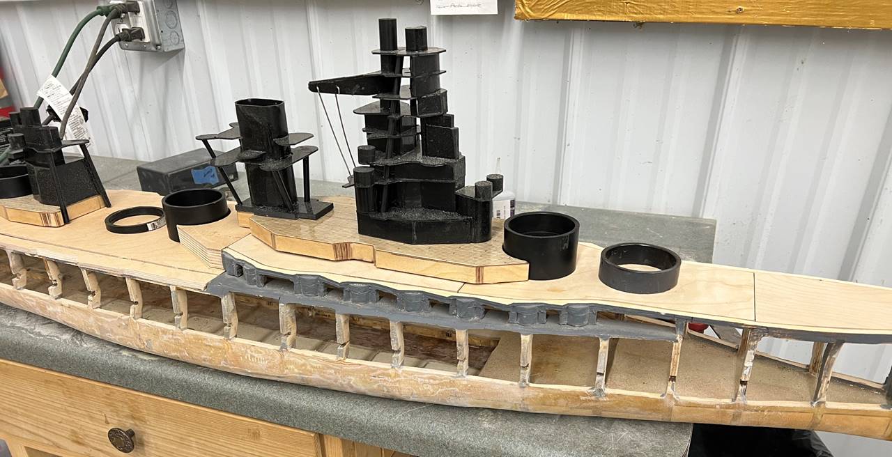
The USS Florida has multiple odd protruding hull
structures. By placing ribs on either side of these structures
you can maximize impenetrable structure since these features also are granted
additional impenetrable material allowances. The bottom picture is from a rough
cut of the fiberglass hull and was further trimmed.
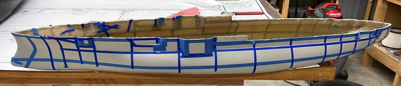
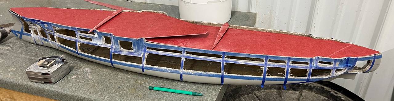
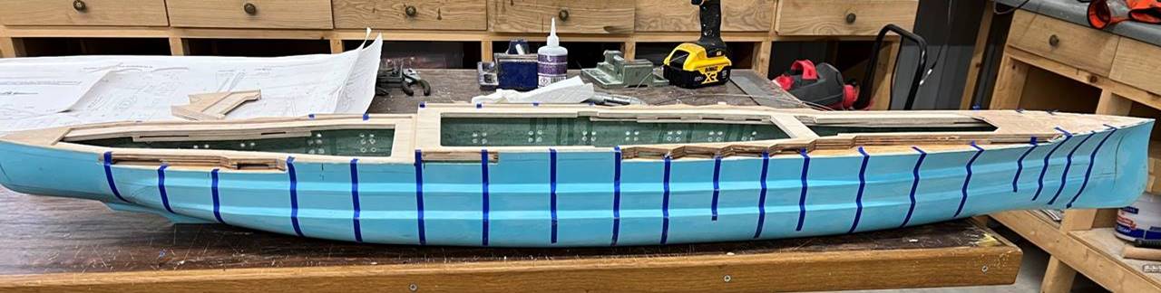
The Vittorio Veneto was a fiberglass hull cut with about
1 inch spacing between ribs in the bow and further spacing the rest of the
ship. Due to play style, this ship should not get caught with sidemounts in the
stern below the step deck and as such the spacing between ribs in the far stern
can be quite generous.
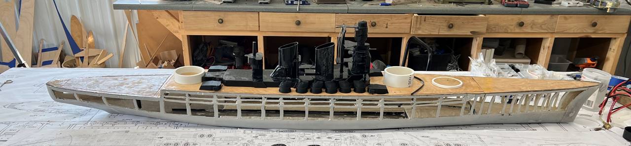
This Nagato is a wood hull ship. The ribs are 1 inch
apart in the bow. The mid ship ribs are placed in coordination with the
casemates, such to keep the casemate opening small. The ribs are again placed
closer together near the stern sidemount location.
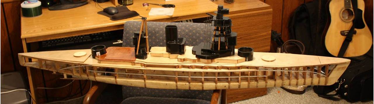
The HMS Barham was cut with clumped ribs
in the bow. The midship ribs were placed in coordination with the casemates.
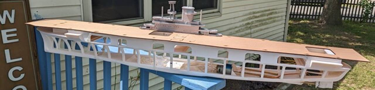
This USS Wasp model is 3D printed and
has uniformly spaced ribs.
Tyler Helland, 7/11/2026