
- Rudders -
Rudders turn the ship. Turning good … makes your
ship good. This article is a discussion about rudders and ways to actuate
them.
Total rudder surface area allowed is
determined by the ship’s battle units. The number of battle units a ship is
designated determines the surface area of the rudder in square inches, with the
minimum allowed being 2 square inches. Thus the 5.5 unit Queen Elizabeth, for
example, gets 5.5 square inches of rudder.
Maximum total rudder thickness is 7/8
inch. This was put in place because rudder designs were getting out of hand
with “fish tail” designs and other odd shapes intending to block thrust with
the rudder itself.
For the most part, two rudder side by side
designs turn better than single rudder ships.
I would be remiss to discuss rudders without talking
about thrust. The drive system has a huge impact on turning and
it is really the relationship between the drive and rudder systems that allow
the ship to turn. This can be conceptualized by imagining a cone of wash coming
off the propeller. Various factors of blade angle make the thrust cone closer
to a cylindrical collum or closer to a conical shape. These factors can have a
huge impact on applying top end speed vs accelerating trust to the ship.
Ideally however, regardless of the shape and the spread of the thrust vortex,
the goal is to have the rudder able to control as much of the propeller thrust
as possible. Commonly, single shaft
ships will be able to get to a reasonable balance of top speed and acceleration
with a slightly larger single propeller but get much better rudder coverage
than two drive prop ships. Additionally, the single drive shaft ships commonly
turn really well in one direction and not as well in the other. This is
balanced relatively by ships that have two drive propellers having better
acceleration due to more overall propeller blade surface but lesser ability to
cover the wash with rudder surface area.
Another important factor in turning are drag
props/disks. My advice is to use drag disks as large as allowable by
the rules. This allows for the thrust to be maximized and more powerful wash
across the rudders generally allows for better control.
The shorter the distances between the stern and
the rudder post is generally favorable. The mechanics of a lever are
such that more force can be generated by extending the distance of the lever.
This is balanced by the shape of the hull and reasonable location of the
propellers.
Rudder shape theory is highly debatable. There are more factors at play than can
easily be tested with high fidelity. A lot of my opinion comes from trial and
error by myself and discussions with veteran captains. In general, I have found
that the rudder height should be considered more important than rudder length.
Having the top of the rudder as close to the hull as possible and slightly
taller (by 1/32 or even 1/8 inch) is my preference. I then put the rest of the
allowable rudder area into length. I typically then use triangle math to extend
the top of the rudder and cut back the bottom edge in various ways. The “fish
tail” on the stern most edge can be helpful, I have found more so in single
rudder designs than dual rudder designs. I typically make the shape of the
rudder convex when looking from the bottom.
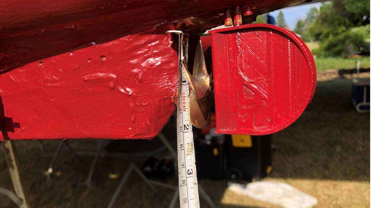
I have seen multiple variations including semi-circular rudders and will
fully admit that other theories can be made to work well.
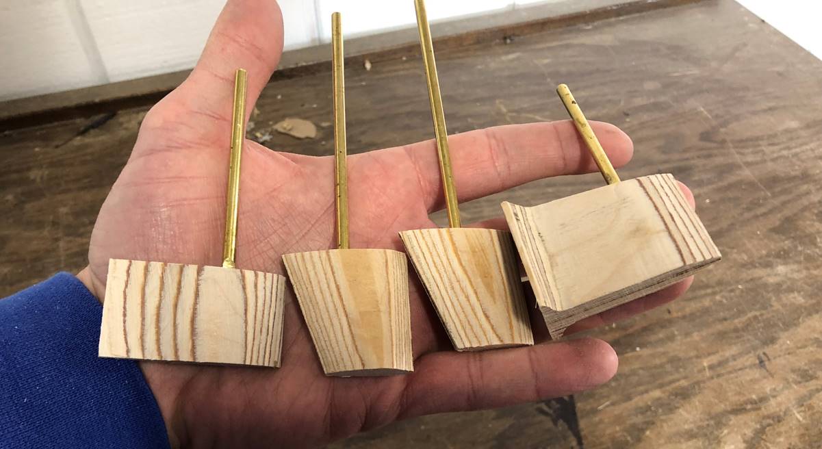
Rudder post
location is also an important variable. I have had the most success with the
post somewhere between the 1/3 and 1/2 point from the forward edge.
Over the years, I have seen a number of clever
solutions for building rudder mechanisms. I prefer a gear on the
rudder post itself, typically with a 5/32 shaft. The smaller gear gets turned by
a large gear, either driven directly by the servo by attaching the gear to the
servo horn when I have the room/clearance, or by using push rods to power the
gear that is anchored in place on a post. Most of the time I use Traxxas 2056
or 2075 waterproof servo because I have had good luck with them in terms of
torque generation, waterproof integrity, and overall reliability. I exclusively
use 32pitch gears. Most of my push rods are 4-40 stainless steel threaded rod
bent to 90 degree angles. I typically use a U-shaped support for the servo
itself and screw in at least one edge and secure the back edge similarly or
with some times a piece of material that swivels. I typically have a support
for the bottom of the rudder to rest on, but allow free drainage as much as
possible. When these servos have failed on me, it has been because pooled water
led to rusting out of the screws on the bottom of the servo itself.
Several examples of rudder linkage systems follow.
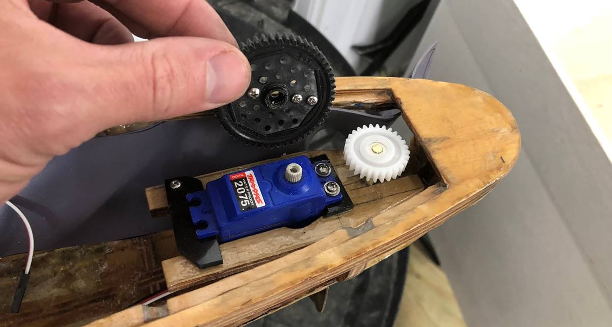
The Tourville has a simple servo horn gear that drives
the single rudder post.
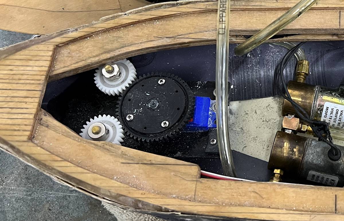
The Viribus Unitis uses a single servo with a gear
attached to the servo horn to drive two rudders.
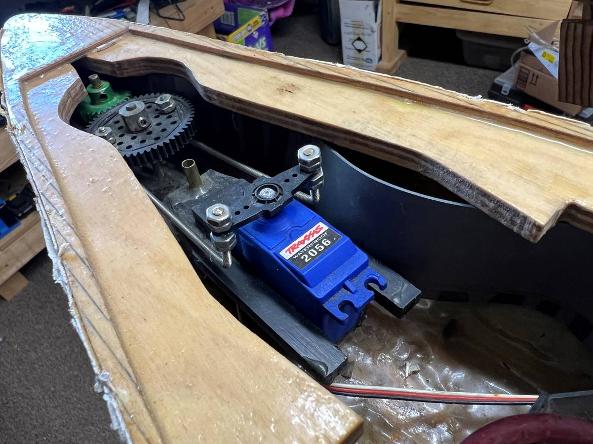
This picture from the SMS Derflinger 2 is showing push
rods that move an anchored gear (black) that then drives the rudder gear
(green).
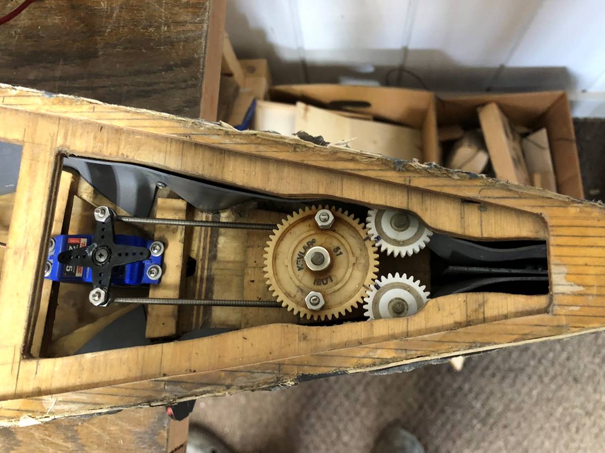
The Kongo uses a push arm to mounted gear method. This
ship has two horizontal braces to which the servo is screwed into rather than
the U-shaped support.
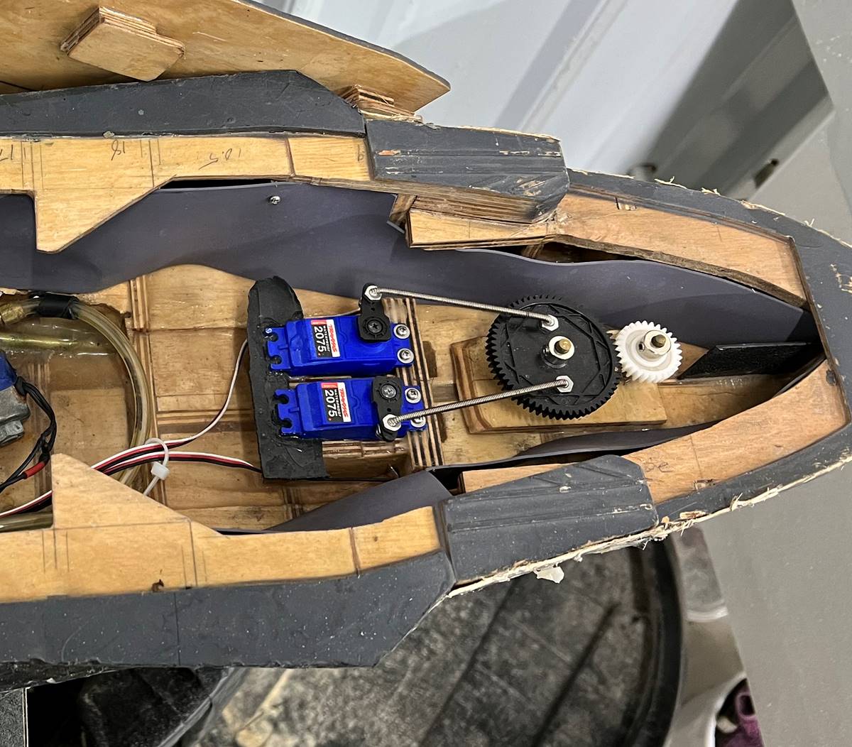
The IJN Yamato has two rudder servos that turn a
single gear that then turns a smaller gear attached to the rudder. This type of
system has to be fairly symmetrical as to not bind itself while trying to turn.
Due to my experiences with my Nagato, I was concerned that a single servo
wouldn’t be able to handle the 8 square inch rudder, so came up with this
solution rather than using a larger more robust servo. It has been reliable.
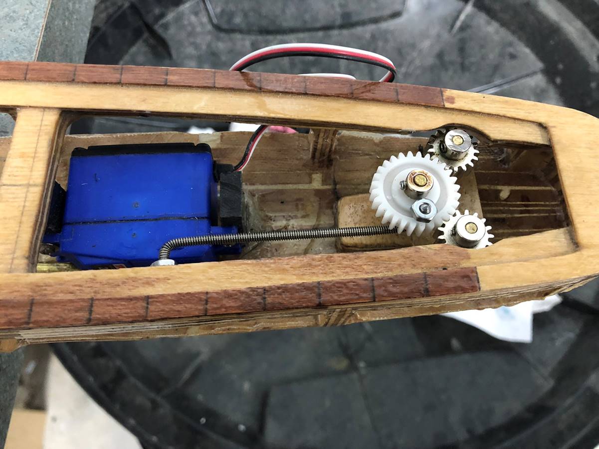
The Akizuki uses a rudder turned sideways due to space
considerations. I generally will not use a single push arm, but the destroyer
can get away with it due to the low torque involved.
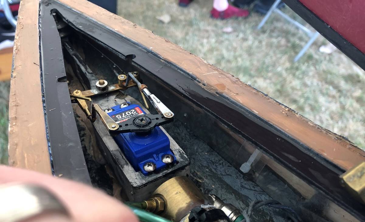
Brian L’s SMS Seydlitz. This ship has a notoriously
skinny stern. Pictured here are various push rods that ultimately directly turn
a piece of material that is attached to the rudder itself. This particular push
rod is not beefy enough for my liking. Also when done this way, the amount of
throw might be reduced.
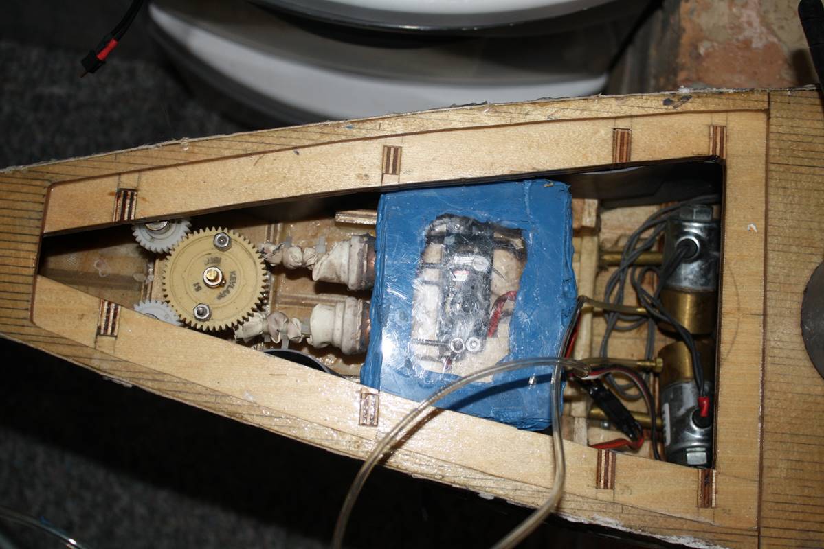
I had to include a picture of the good old days, before
reliable waterproof servos were commercially available. This is a waterproofed
box, with arms extending through holes in the box that were then sealed with
balloons. It worked fairly well but failed enough to cause missed battles,
typically when this got wet it shut down your day. This is a sideways mounted
very high torque rudder, the first one I had in this ship stalled out under the
load of a full turn.
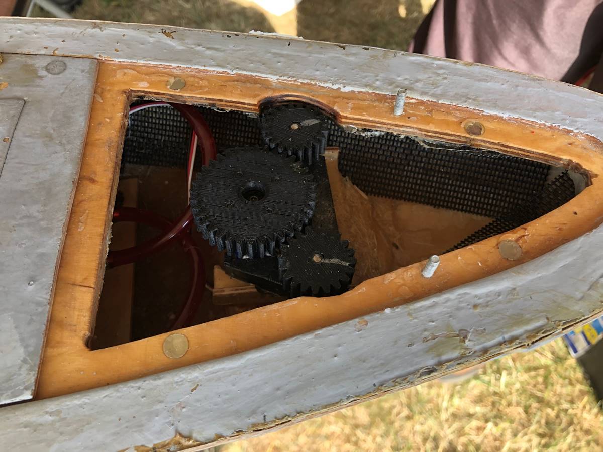
Kevin P’s Iowa uses a recognizable approach with a different
style gear than I use. This style of gear is common and reliable.
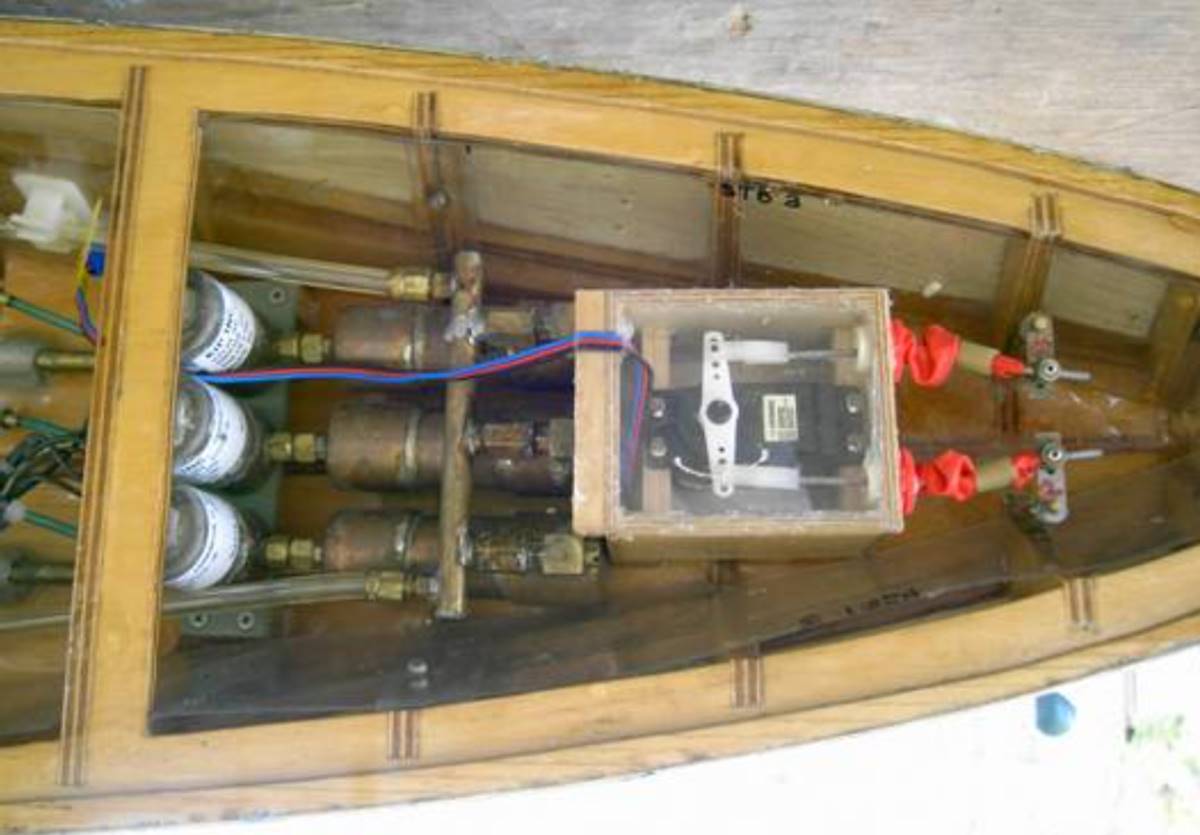
This is an old picture from Charlie’s North Carolina.
The rudder linkages are the direct to post style, which limits throw to some
extent.
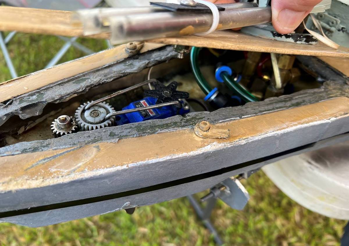
Mike’s Seydtliz has push rods to a small gear (35T)
that drives an even smaller gear. Using smaller gears saves space. The deck
itself holds the push rods from coming loose which makes adjustments easy but
is precariously insecure in my opinion.
Other recommendations and pitfalls
Whenever possible for most parts of your ship, use
stainless steel hardware.
Binding and too much friction can be a huge problem.
Regardless of of the mechanisms used to set up the rudder, of use care to be
sure the components have enough play to move freely when the servo is not
attached.
Too much play can also be a problem. If the components
are not snug enough, the ship will be difficult to control or be prone to
slipping gears.
Too little torque is a common problem on larger ships with
larger props and rudders. In general plan for overkill, if the servo doesn’t
have to work hard it will be much less prone to failure.
Experiment with different setups. I can think of no
better example than of Kevin’s Missouri (see below). He built it with 3 rudder
post sleeves inline with an adjustable larger gear and experimented repeatedly
with different shapes and rudder post positions to get his ship finely tuned.
Most of the time however, if you follow the general principles I have
discussed, you should have a pretty close starting point.
Tyler Helland 7/19/2026