
- Viribus Unitis -
SMS Viribus Unitis– Tyler (2020)
4.0 units, 28 seconds, Austro-Hungarian Dreadnaught
style Battleship launched 1911
The Viribus Unitis (VU) is a pudgy little Dreadnaught with
an impressive amount of fire power potential for it’s tiny size. In scale it is
41.58 inches long, 7.5 inches wide, and 18.15 lbs. There is a significant
portion of the middle of the ship with casemated guns, making for very little
target area amidships. It is slow at 28 seconds but given the small weight and
short length when combined with twin rudders it should be very maneuverable.
Another interesting aspect of this ship that I was drawn to is the fact that it
has four separate primary turrets with three guns each, making for multiple
possibilities for gun setup. I’ve been wanting to do a small well turning boat
for a while since primarily I have built the 24 second battleships and
battlecruisers. This will likely be the ship my son uses to learn sidemounts
since it should be relatively forgiving in close quarters.
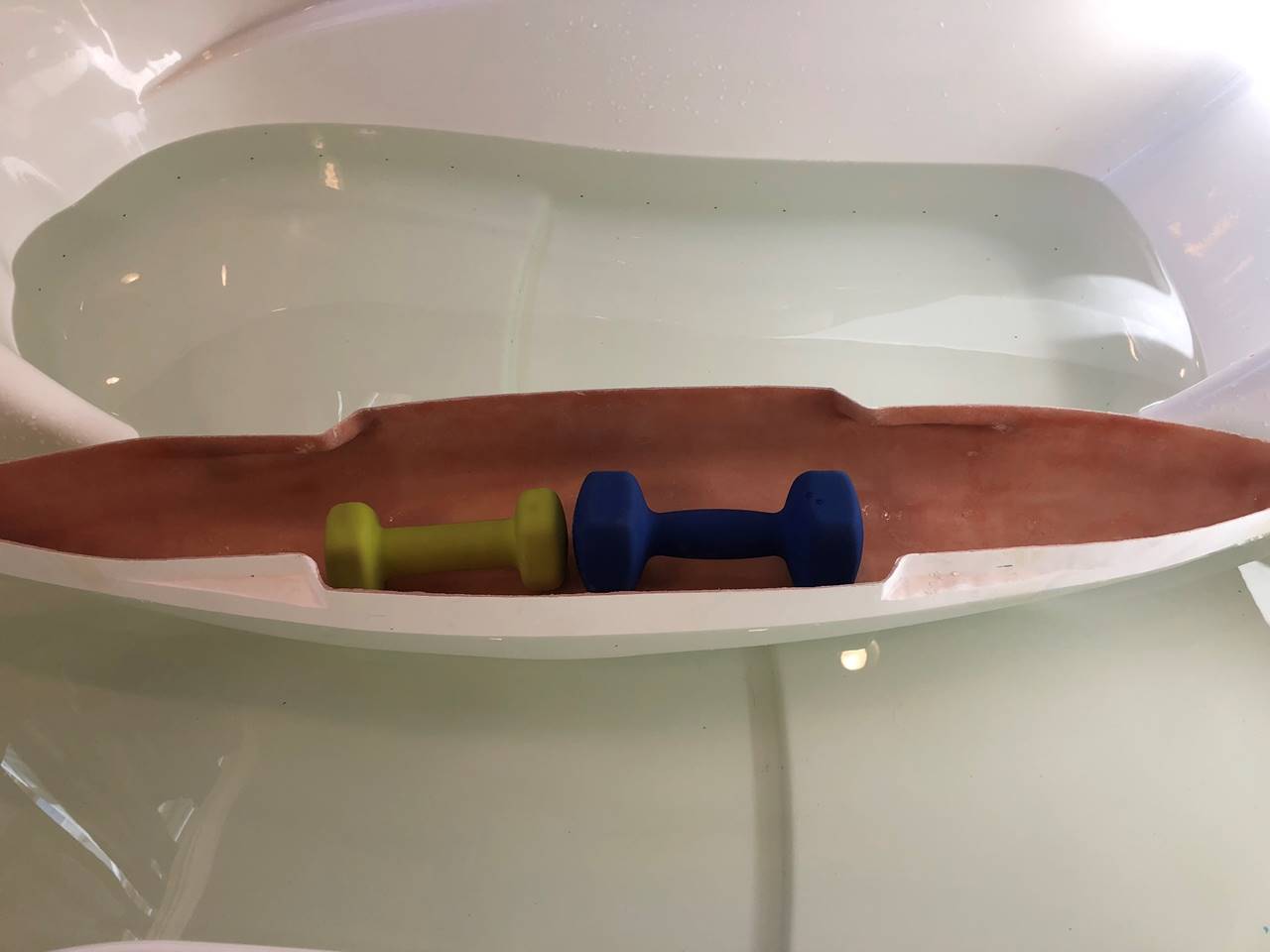
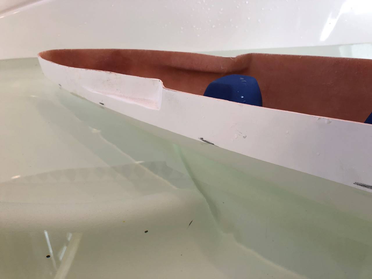
An advantage of fiberglass hulls vs wood hulls is that
you can float them at what you think battling weight will be as the first step
in building. This allows you to measure where the water line directly and thus
the 1 inch below measurement where the windows will be cut out is fairly
accurate and based on an actual measurement. This ship fits in a bathtub
easily, some of the bigger ones don’t. 15lbs of weight + 2 lbs roughly of hull should
be close. I purposely float it slightly light so the 1 inch below the water
line is very slightly deeper than it would otherwise need to be in case the
build ends up light. I expect this ship will be best off right at 18lbs
however.
Pencil will work even in water. The ship is shifted to
show the lines better for the picture. Be aware of both front to back and side
to side trim when doing this. Any little ripple in the water will mess you up
so take the time to do it right, the rest of the build hinges on this step.
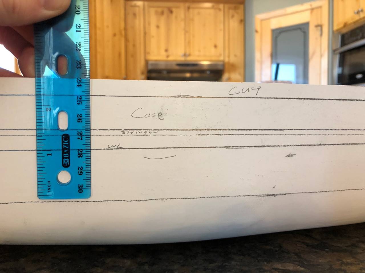
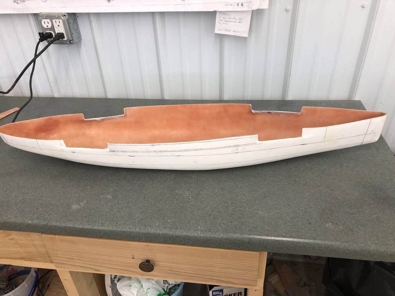
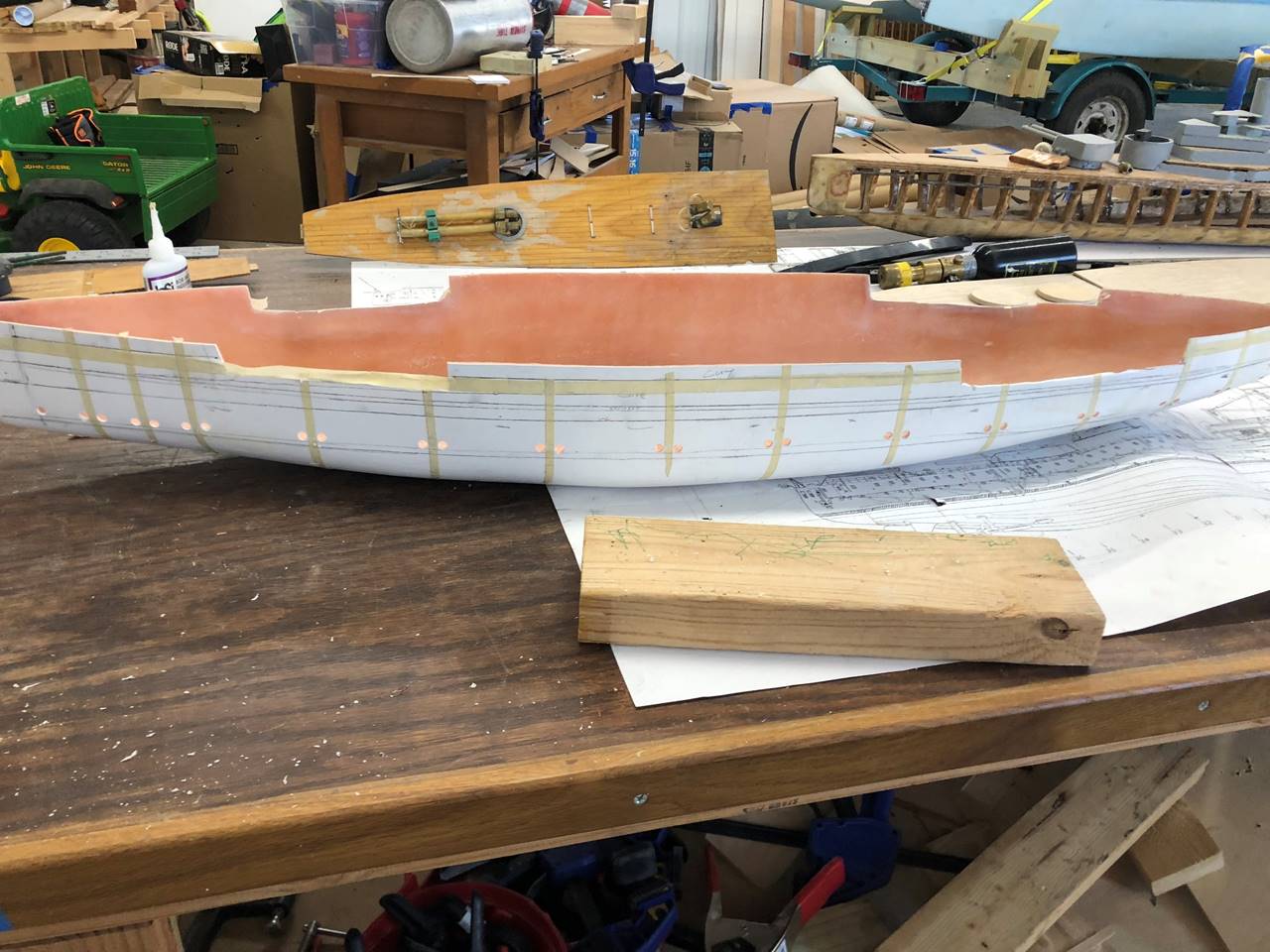
I drew out the major landmarks with pencil right on
the side of the hull. “WL” is for the waterline, and you can see the
1-inch-below mark as well. Since I was already floating light I think I will
probably move the 1 inch below cut to the actual 1 inch mark rather than 1 and
1/8 inch it is currently at. Ultimately 1/8 inch too deep isn’t a big concern
and I might leave it as marked for reserve room to not be too shallow. The
stringer is an 1/8 inch section where the casemate deck level sits. The “case”
section is where the actual casemate guns will sit. The “CUT” section is
actually going to be removed. After measuring the fiberglass hull against the
fairly decent plans I have access to, the fiberglass hull is roughly 3/8 too
tall all throughout, and the indentations for the casemate sections are also
slightly incorrect in positioning. I will be able to deal with this fairly
easily with a Dremel tool. The ram bow is also modeled incorrectly on this
hull, I haven’t decided yet if I’m going to leave it or fix it. The bottom of
the hull seems fairly close to the plan set I have. I had planned to build the
deck/subdeck assembly before I cut the hull out, this will allow me to line up
the stringer/casemate section pretty accurately.
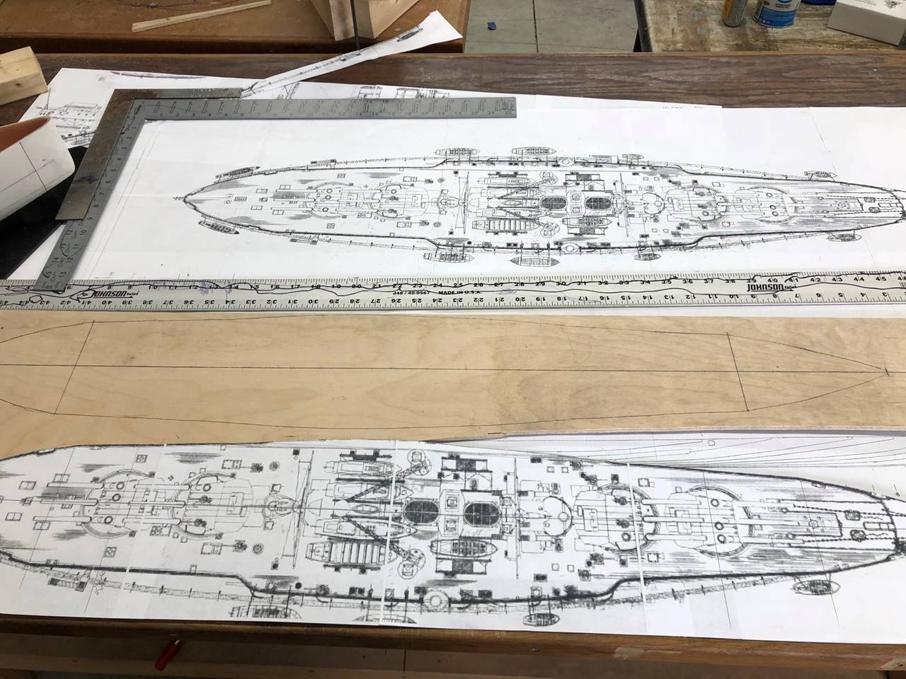
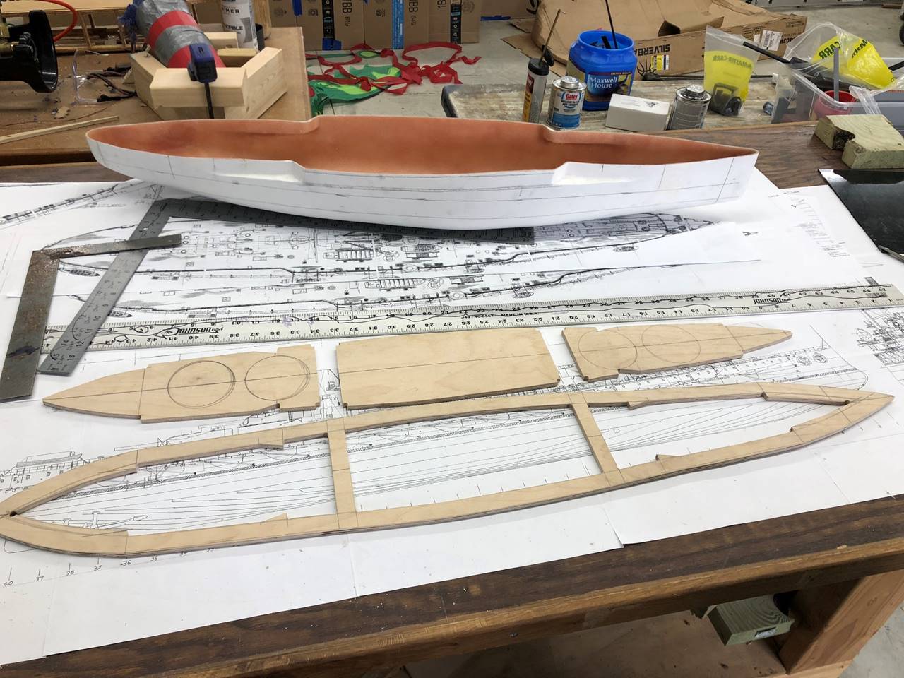
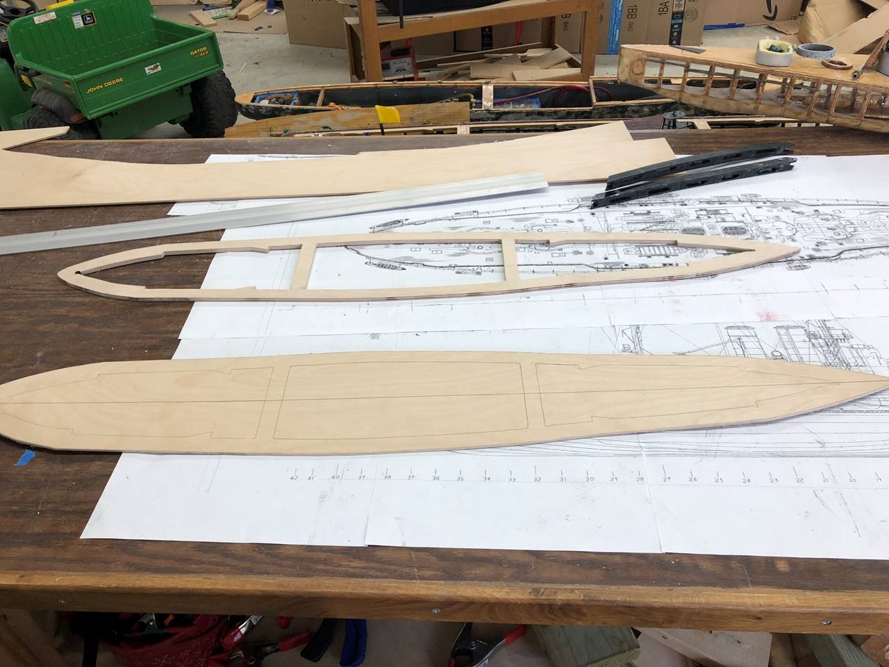
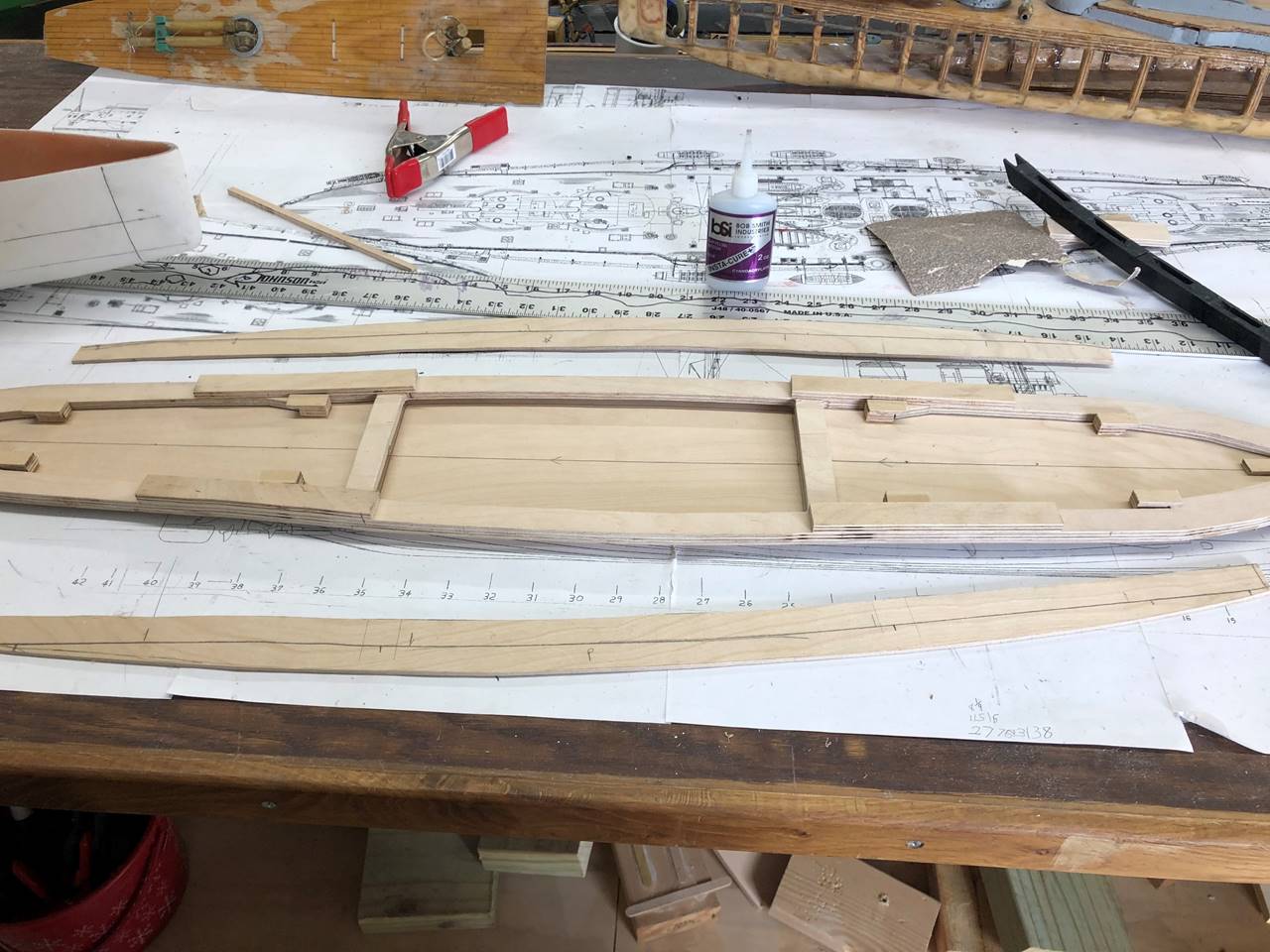
The deck/subdeck can be traced from the fiberglass
hull if you trust it, or from a set of plans. The higher level of the deck will
actually have minimal contact with the fiber glass in this ship, so I elected
to mark out the outline from a plan set. I generally would advise starting with
the subdeck. This is ¼ inch 5 ply birch plywood. I started with a straight edge
center line mark and drew half the outline, flipped it over and drew the other
half as to maximize symmetry.
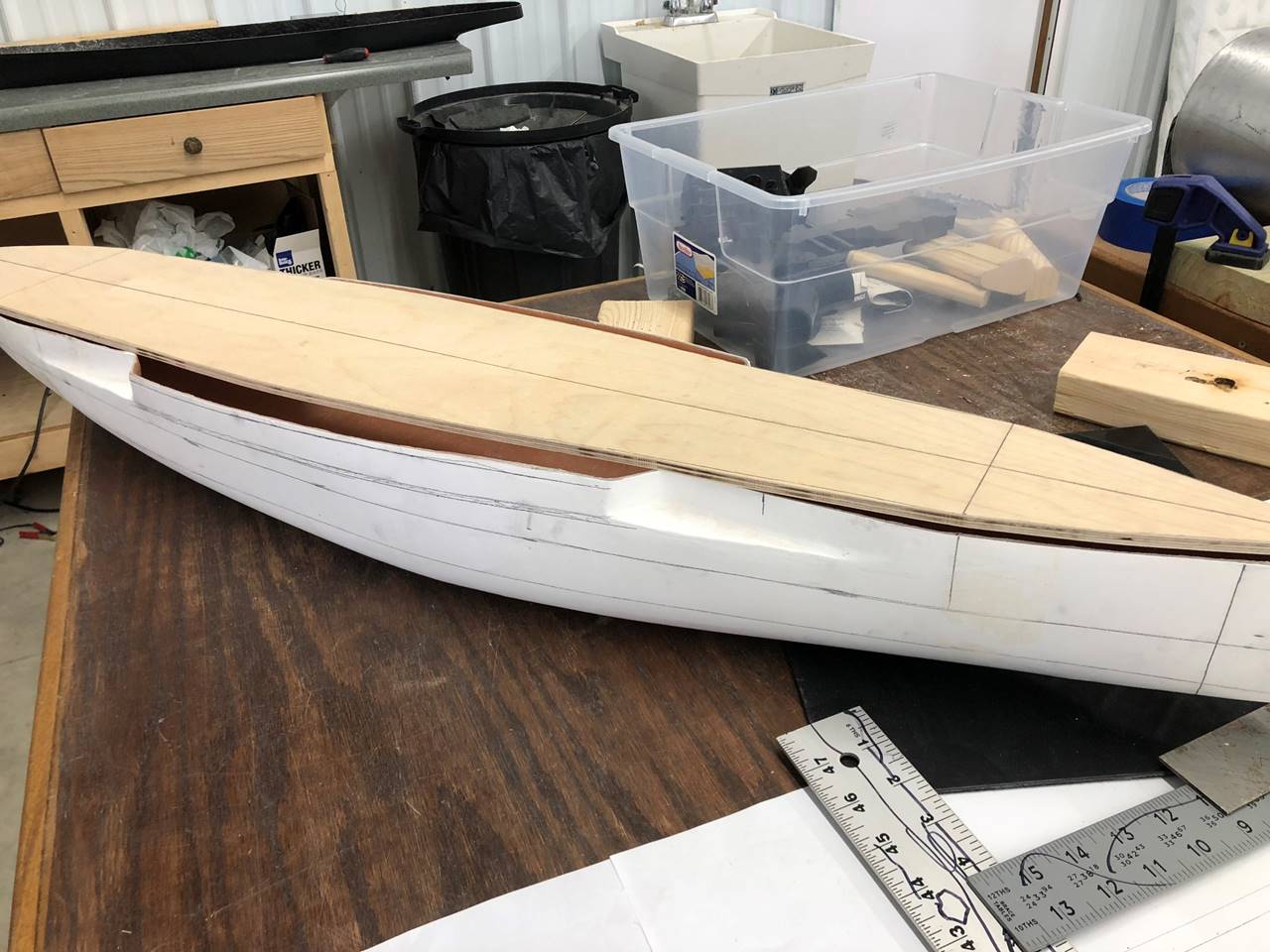
Here is the subdeck on top of the fiberglass hull. The
mid-section fiberglass casemate area will be cut out and made completely out of
ABS plastic. Only the far bow and stern will have contact with the hull.
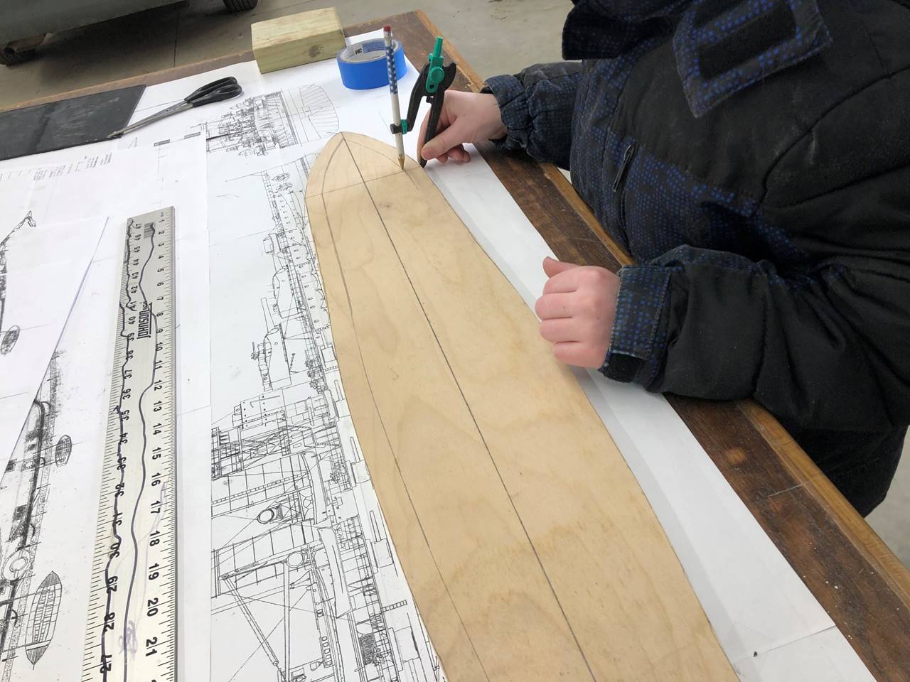
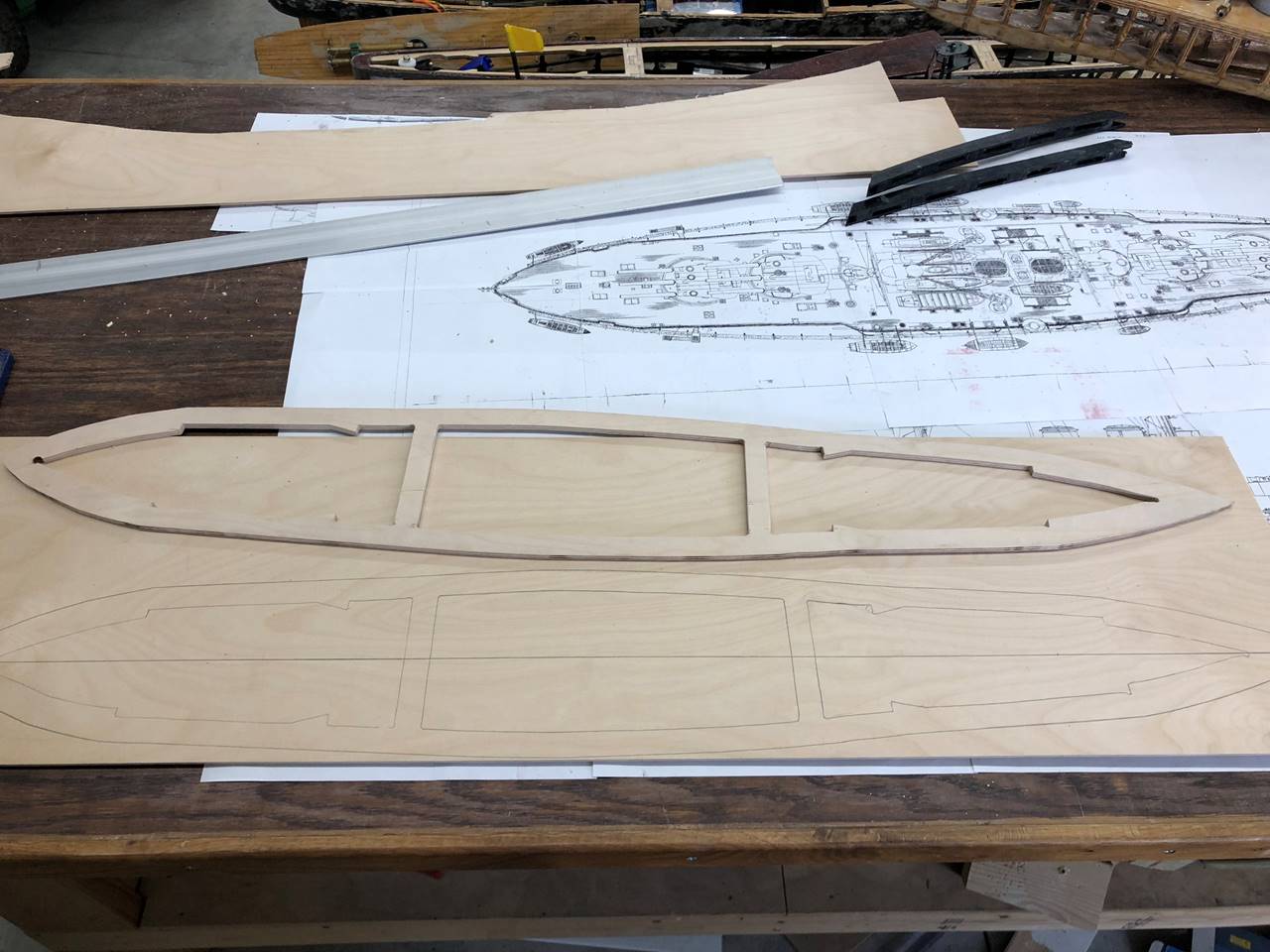
The center of the sub deck needs to be cut out. I
generally use a compass to get a uniform subdeck thickness. Additionally, any
cross braces, support structures, and deck latching will need to be marked out
to be left behind. Depending on the
ship, this is usually 3/4 to 1 inch wide sub deck in most of my ships.
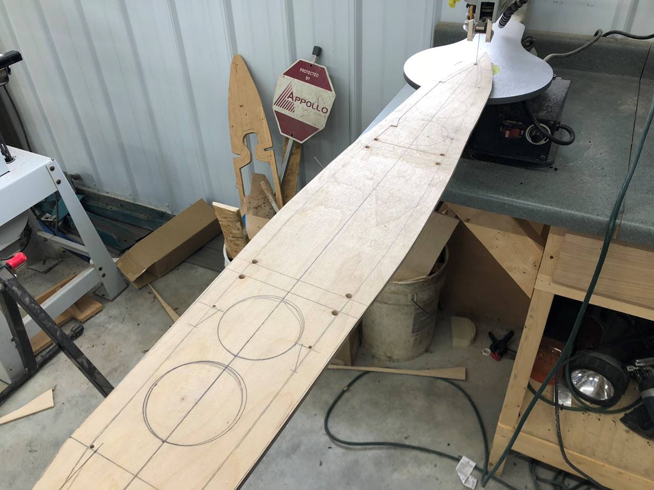
I started cutting before I took the picture so here is
right after I started in with the scroll saw. I marked all cross braces and
deck latches. I also would suggest using a drill to take the corners out both
as a point to more easily turn the scroll saw and insert the blade, but also to
keep the corners strong via curvature and prevent over cutting.
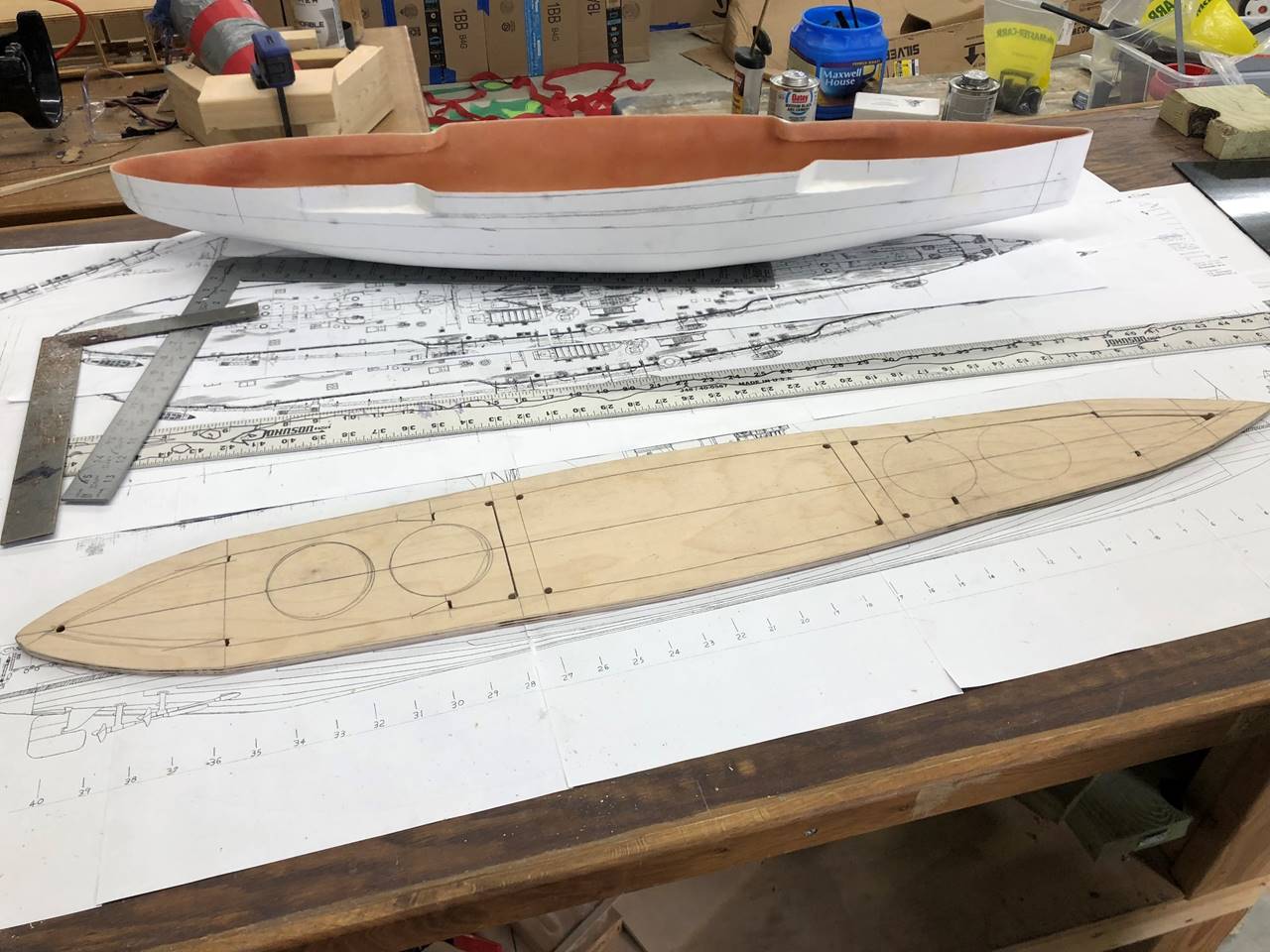
All pieces are cut from the subdeck.
Subdeck is cut. You can see there are two cross braces
on either side of the barbettes. I’m still contemplating gun setup at this
point in the build so I wanted to leave structural supports compatible with use
of any of the turrets in the future.
Since the casemates will take an absolute pounding,
I’ve opted to make them completely out of ABS and slap them on to the side of
the wood subdeck.
I cut out the area of the casemates that were not
correct within the hull itself. Essentially this is at the corners where the
deck steps back along the casemate level.
With the 1/4 inch subdeck as a stencil the actual 1/8
inch thick deck is relatively easy.
This picture is pretty redundant but I was trying to
keep good records.
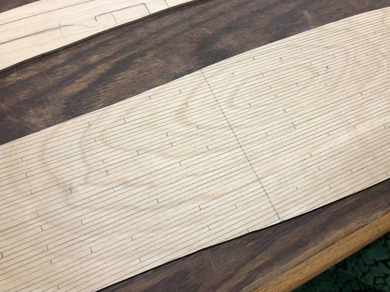
I love making planking on the deck with pencil lines
and rulers (1/8 inch spacing) not because of the process, but because the end
result is really cool looking. An epoxy layer over the top keeps it protected.
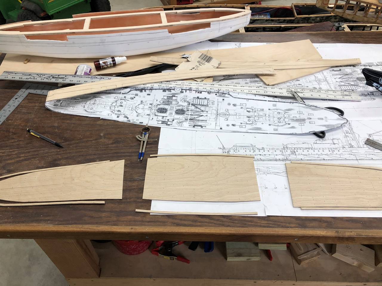
I use a compass to measure then cut the edge out of
the 1/8 inch deck to glue permanently to the subdeck. It is about 1/4 inch
thick on most of my ships.
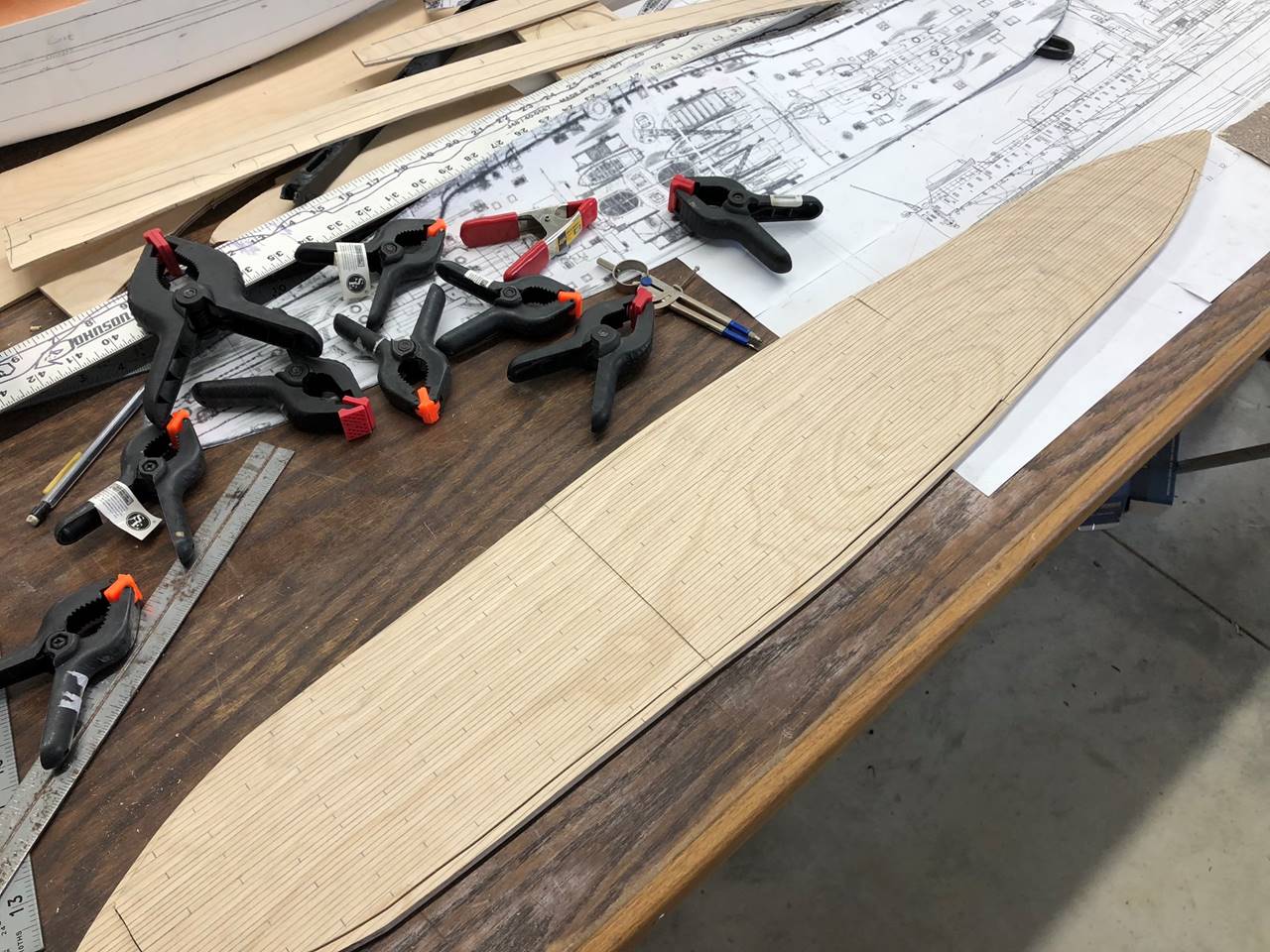
This picture shows the subdeck and outer deck rim
glued together. The deck is cut into 3 sections. The stern and bow most have
the turrets, the middle section has the bulk of the superstructure. The stern
and bow sections slide into place and lock with latches that are under the
deck. The middle section will have magnets inset to the deck and subdeck.
Hopefully the magnets will be strong enough to hold it together.
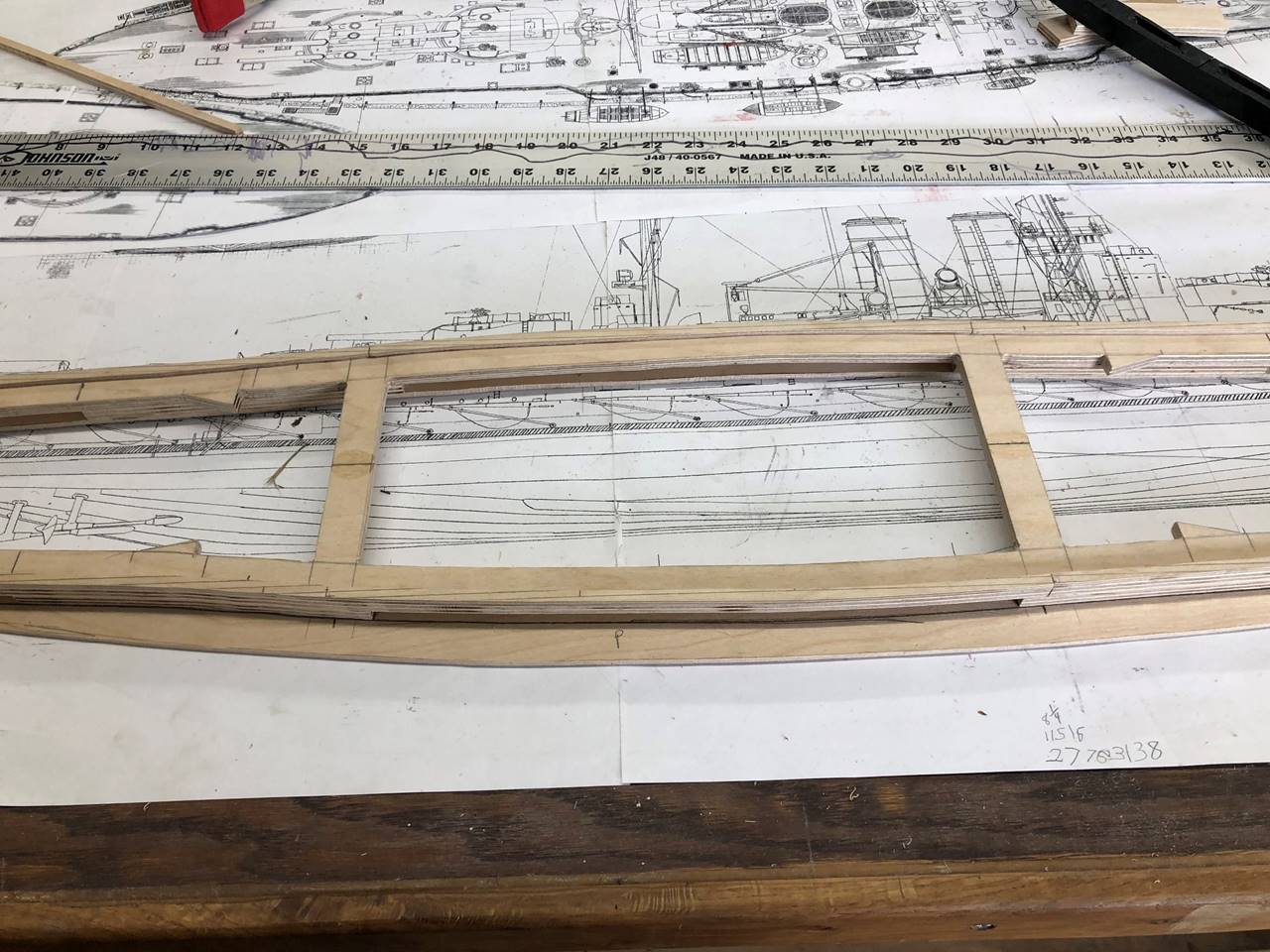
This will start to get confusing for the untrained
eye. I am building the entire deck/subdeck/casemate assembly as one unit built
upside down. You can see the deck slide latching system in the bow and the
stern. The gap between the casemate level and subdeck is 1/4 inch, so I just
layed out 1/4 inch ply wood in areas that are allowed to be solid. The 1/8 inch
thick casemate level has markings where everything will line up.
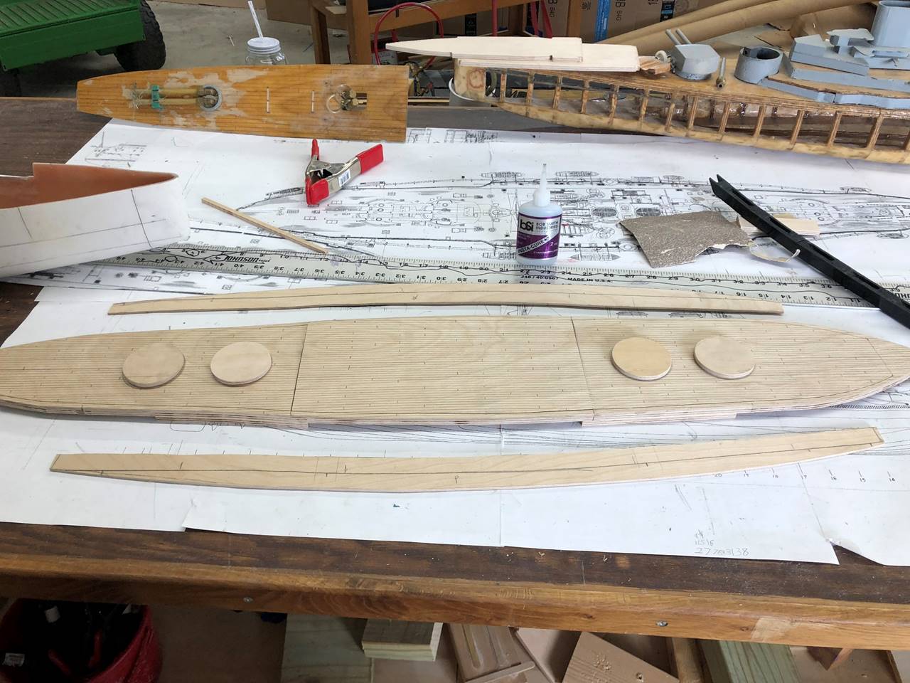
This is basically the previous picture flipped right
side up. The barbettes will be made of ABS pipe but I like to put a 1/4 inch
thick ply wood circle to hold it all together better.
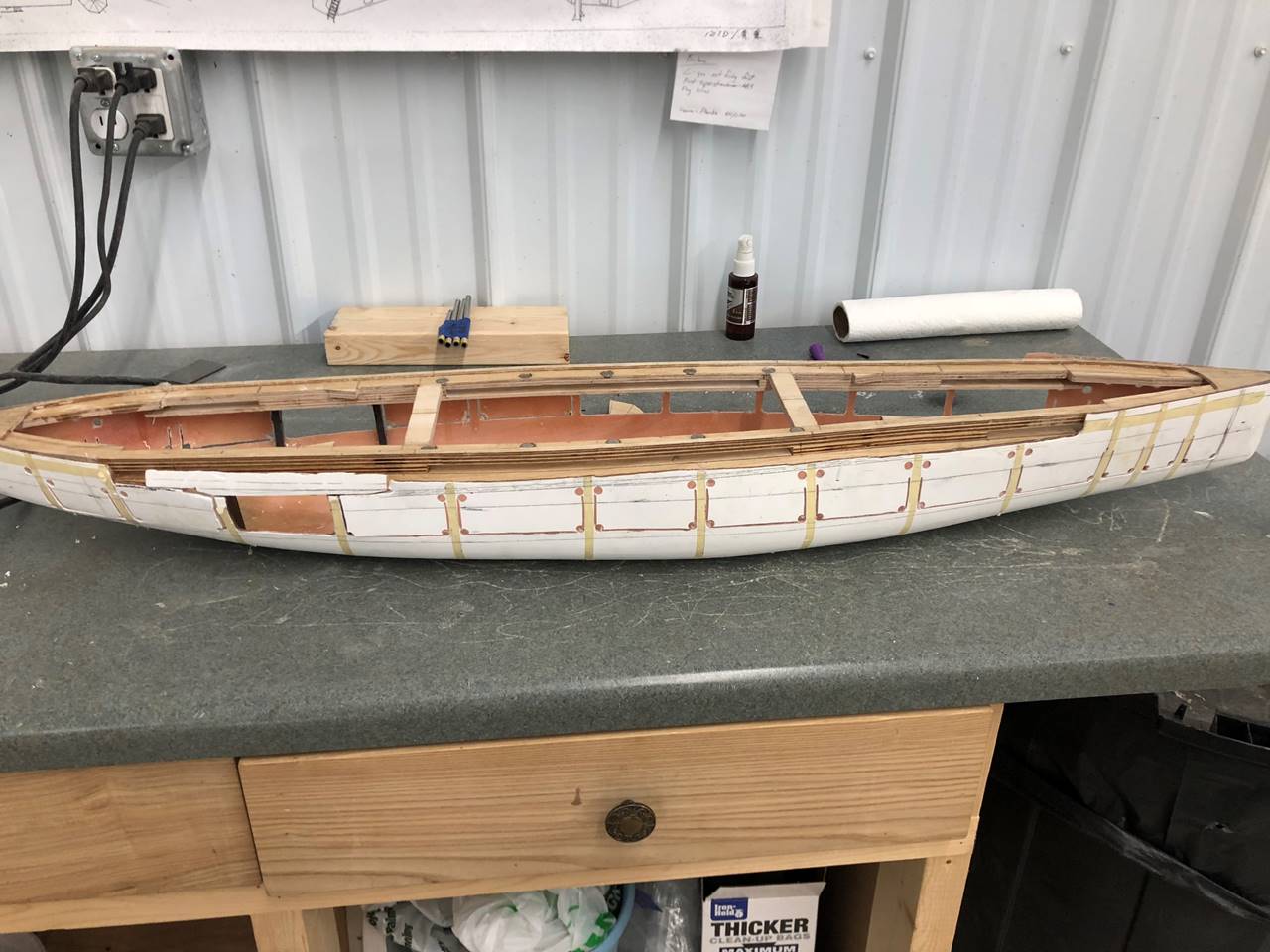
The decks are removed, this is right side up. The casemate
level is now glued in. I always label port and starboard as I go so I don’t get
things flipped.
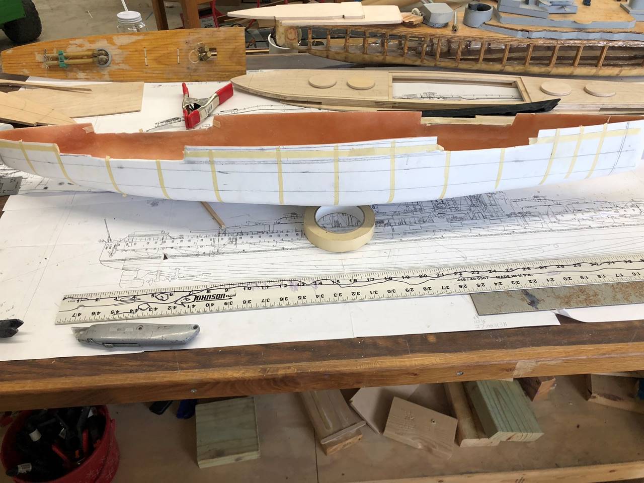
I generally use tape to mark out where the ribs and
subdeck will go before cut. This usually takes a lot of planning and trying to
get ribs to line up more densely in the bow.
I would recommend drilling the corners of the
fiberglass as to help avoid over cutting with a Dremel. As I have stated,
fiberglass hull was too tall and required trimming.
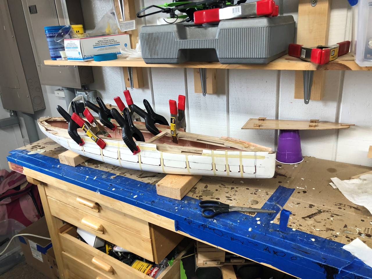
I put the deck/subdeck assembly in with the hull
partially cut. I did this to give the fiberglass more flexibility to glue it
in, but this will not allow me to easily over cut the casemate area when I do
gut the rest of it out.
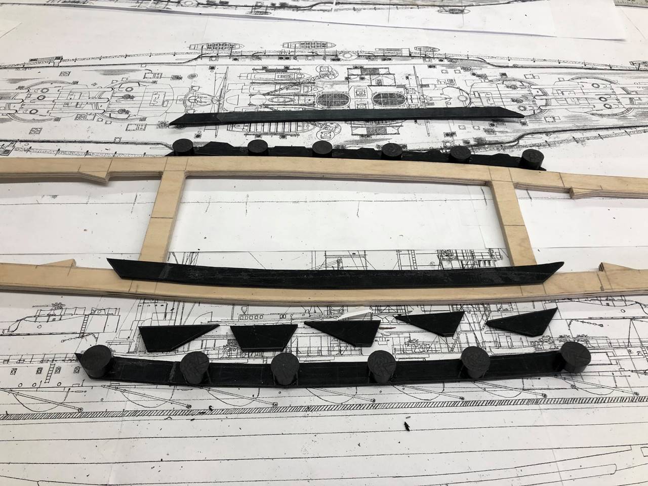
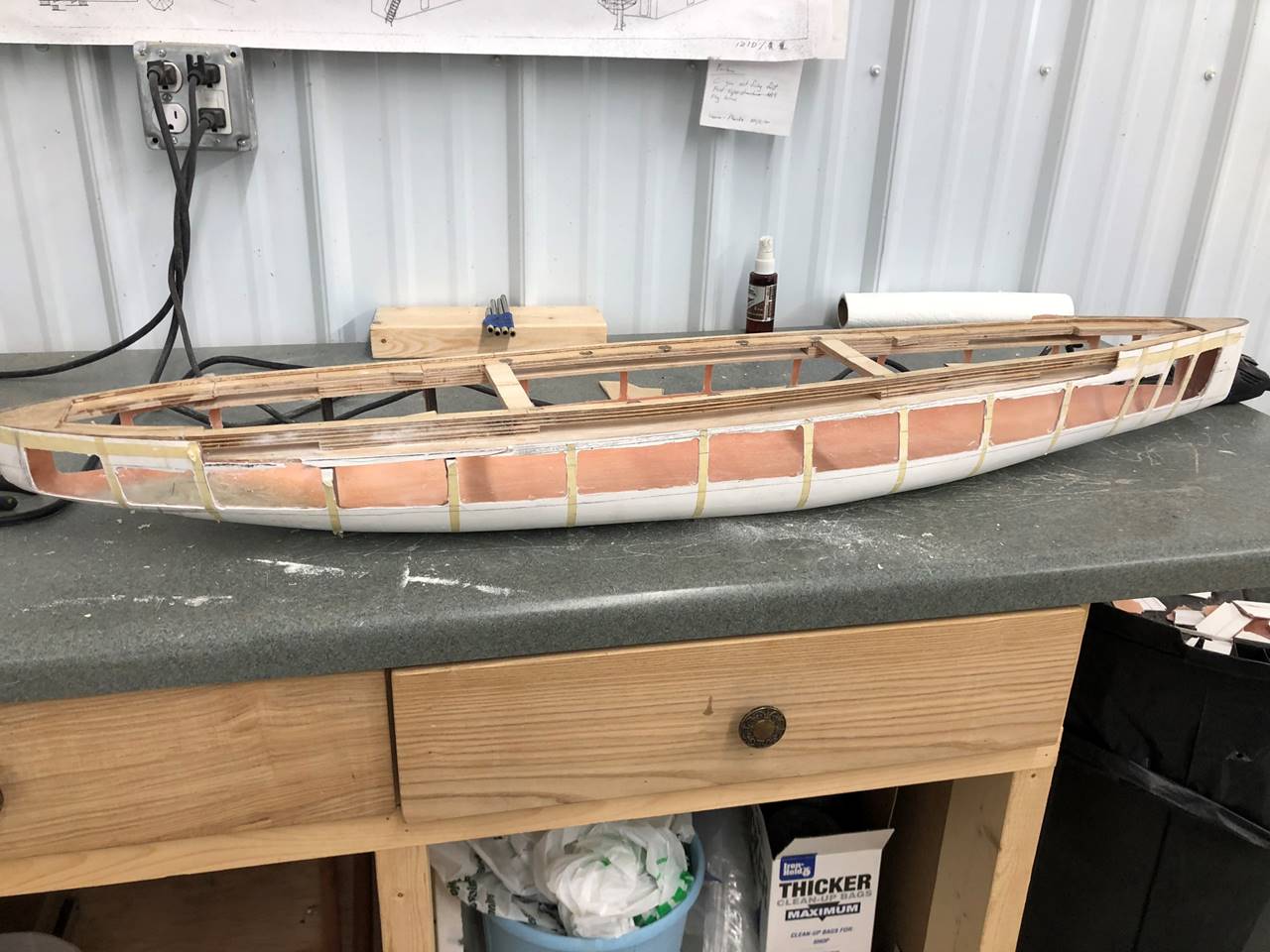
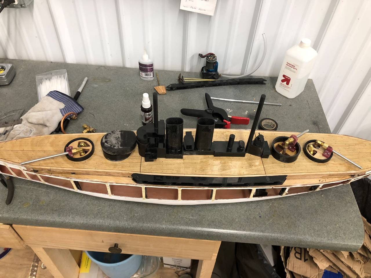
I love putting the parts that I have completed on the
ship to give a sense of how far it has come and keep myself excited. The
superstructure is made from ABS sheets per my usual method. Very strong and
relatively easy to build. It is all 1/8 inch thick, I should have made the
funnels 1/16 to save weight.
After the deck/subdeck assembly was glued and epoxied
in, I drilled the top edges of the “windows” and started cutting.
Getting closer.
The “windows” are cut out but I wanted to apply epoxy to the underside of the
subdeck and casemate deck as it sat upside down to get everything to hold in
place better before I attacked the rough edges and smoothed them out.
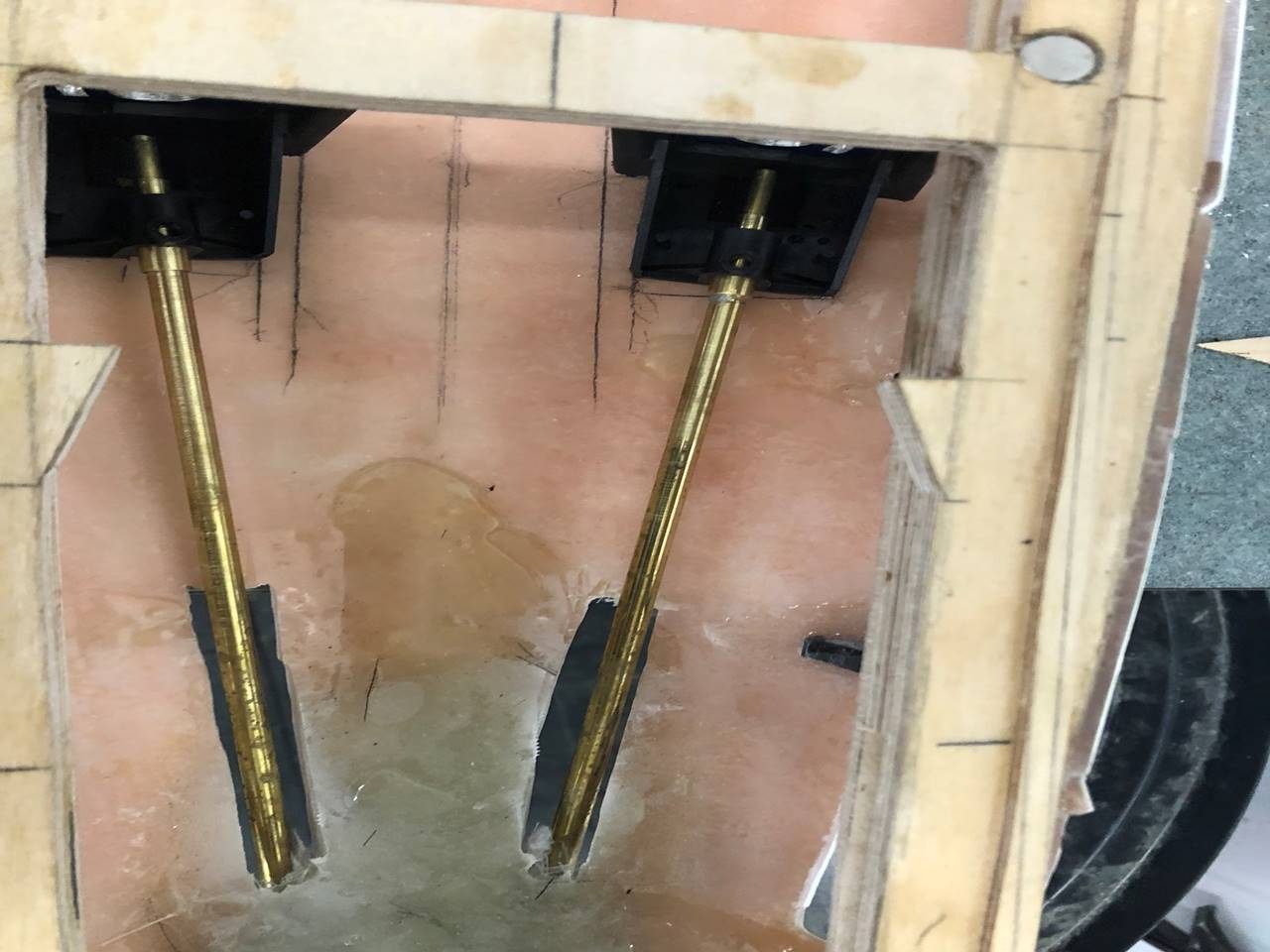
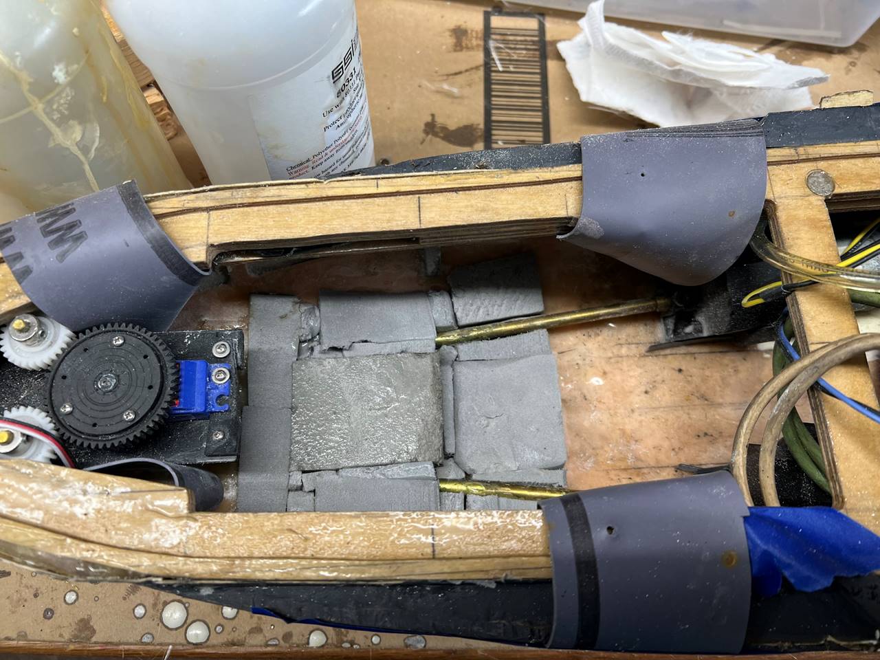
The shafts and
gear boxes for the motors being installed. I marked the center line of the ship
as well as where I thought a water channel might go with pencil.
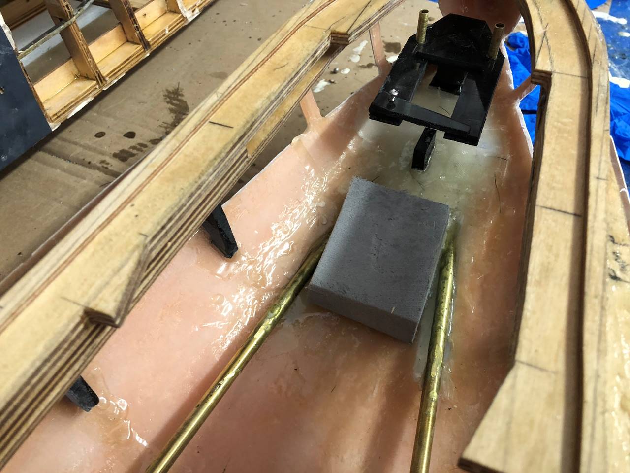
The bow water channeling underlying foam, it would
later be covered with liquid plastic and micro-balloons.
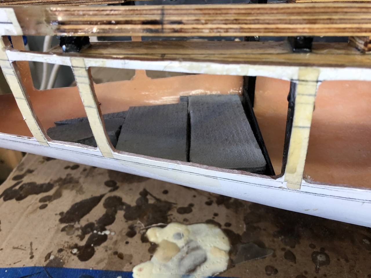
The stern water channeling is just a block of foam to
start with, I’m not sure how I wanted to do this at the time but would eventually
put more foam/plastic in.
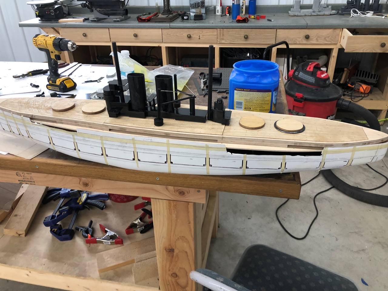
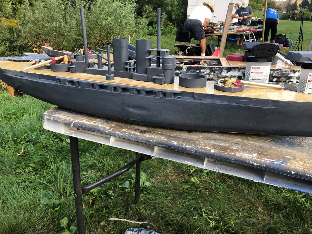
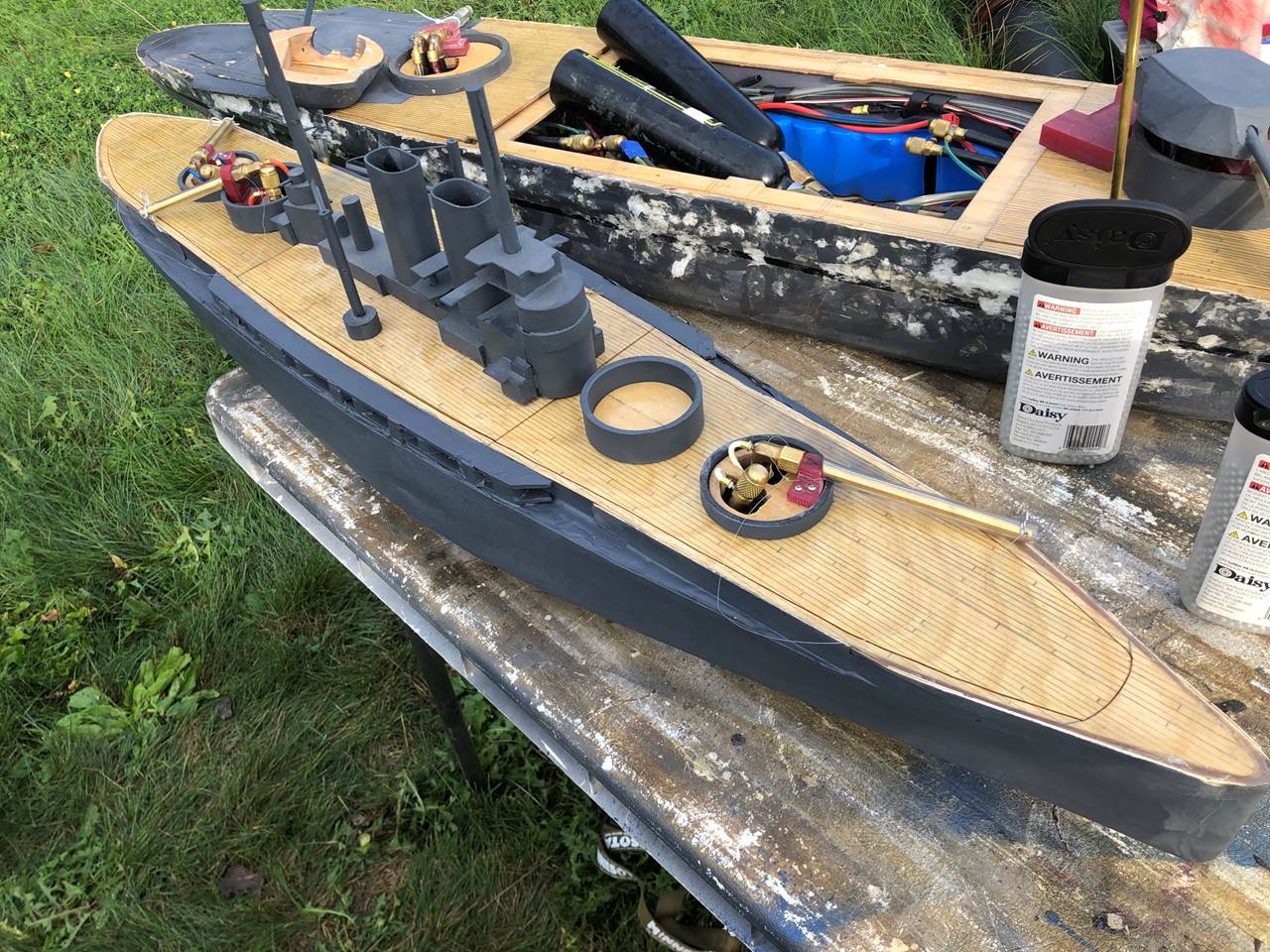
The super structure was fairly simplistic on this
ship. I built it out of ABS plastic. This is the gun setup I planned to start
with. Some would call it the “Death Y” and I would call it two haymakers with a
funny gun. I think a more traditional bow sidemount, stern sidemount, stern gun
would probably work well also. There is a ton of flexibility though with the
triple gun turrets so you could run triple stern guns in this vs twin sterns and
a haymaker vs the option for several other in my opinion less effective setups.
You can see the deck planking drawn with pencil. Also you can see the casemate
area of black plastic I’ve glued to the outside of the ship at the time of this
picture.
VU before her first battle 9/10/2022. I finished a lot
of little things in a big hurry to get it on the water and planned to take
pictures of internals later when the water channeling and internal
configuration was formalized. On the water she was very quick and hard to pin
down as expected. At this point however there was not midships water channeling
or any sort of lock down mechanisms for the batteries, radio box, or CO2
container.
I always seem to struggle to get the turrets put on
before the first battle. After this first outing and another 11 sorites the
next spring I was settled on the proper internal configuration and was ready to
commit to further internal improvements.
This is the stern water channel foam, usually where
there are sharp curves and features to work around it becomes a patchwork. It
will fill in fine with 2 part liquid to solid plastic or epoxy. The rudder
setup is shown. The stern solenoids will sit on top of the water channel. The
pump sits under the cross brace between the motor mounts.
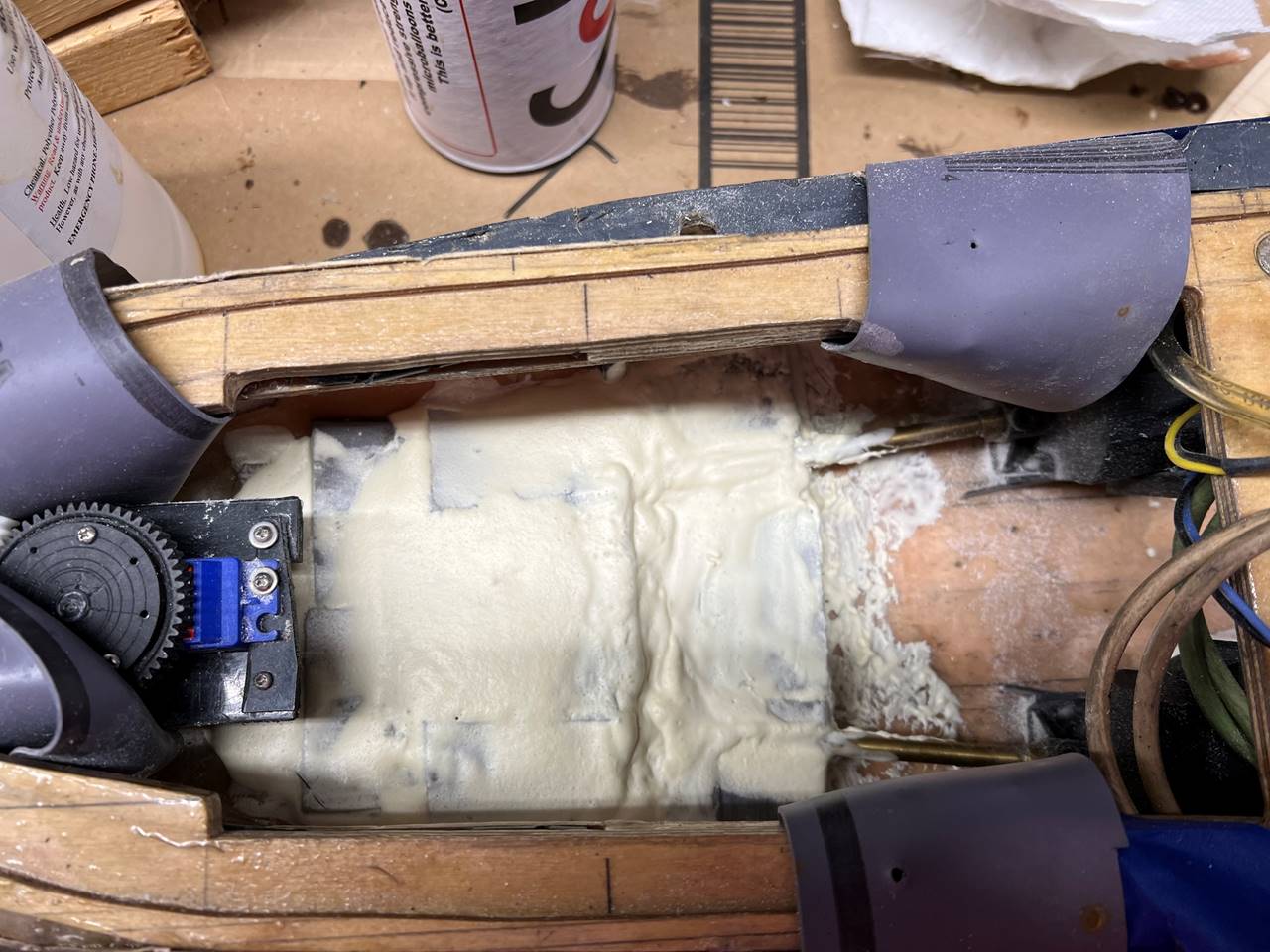
Plastic + microballoons filled in the water channel
foam gaps nicely. It’s a little clumpy but that isn’t a big deal. I may sand it smooth in the future.
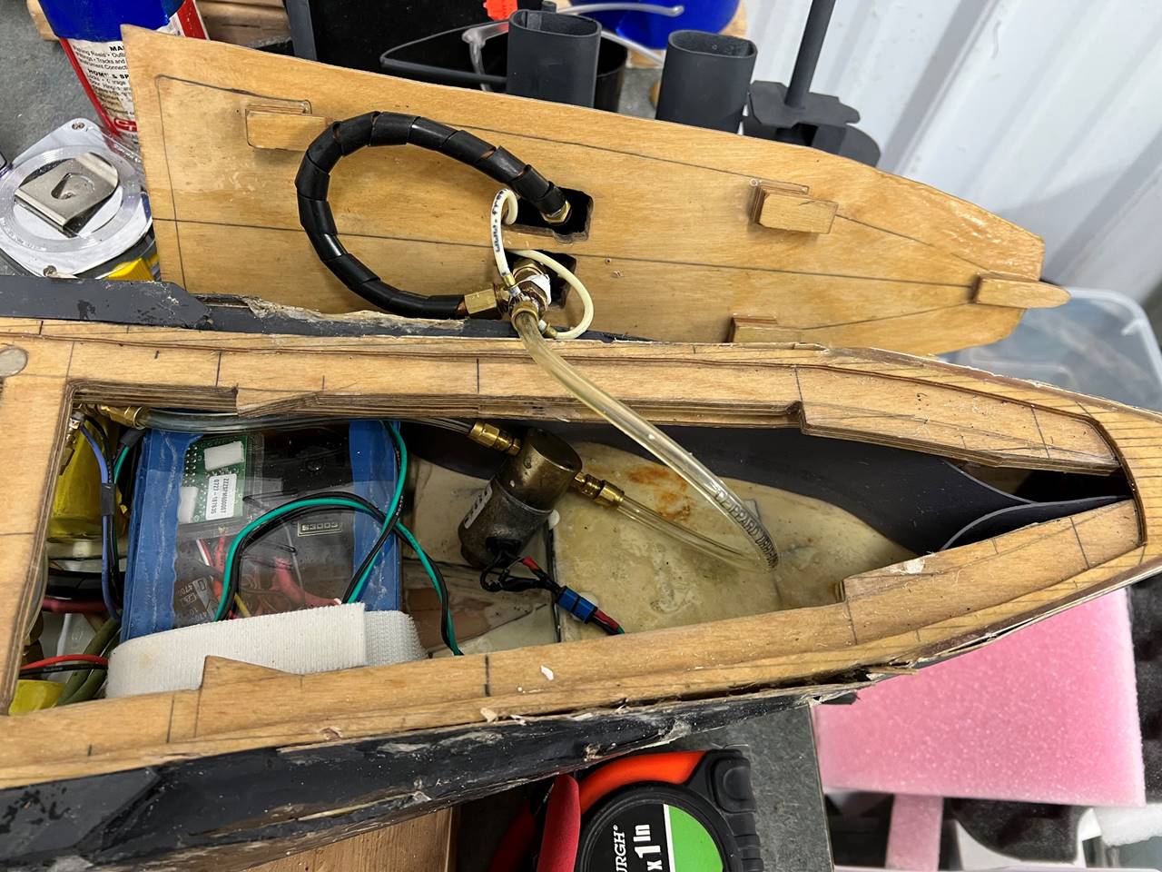
Fully loaded bow. Water channeling in the front almost
goes to the bottom of the window, there is a step down to just ¼ inch tall
water channeling along both sides of the ship with a gap in the middle that
runs from that point to the motor mounts. The solenoid is seen with room for the
gun to stick through is next followed by the water tight radio box which gets
held down with Velcro. Eventually when I figure out for sure how the balance of
this ship should be, I will tie down the solenoid. The cross brace is the
dividing line for the front deck section which latches in with the slides seen.
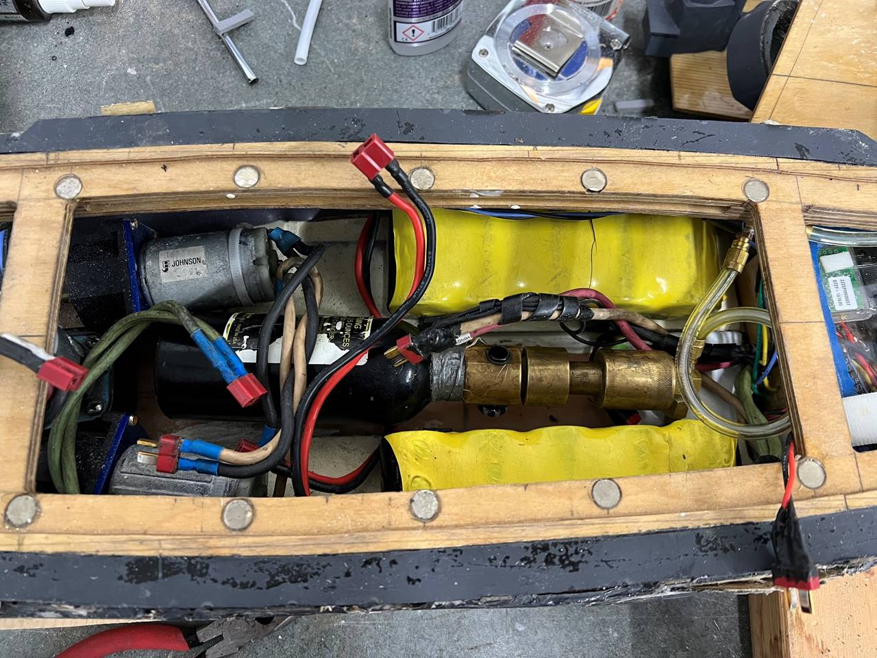
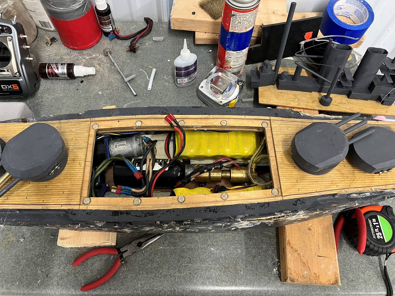
Middle of the ship holds the batteries on either side with
the bottle/solenoid down the middle. In a small ship if you can get the bottle
to sneak between the motors/motor mounts it can save a ton of longitudinal space.
There is also a AAA receiver battery pack under the regulator which is very
difficult to see in this picture. I was initially running this with 3 of the
10ah 6V NiMh packs but it weighed in a little heavy. A full battle was drawing
15 amps so with the reduction down to 2 batteries I will switch them between
sorties. I was having receiver/transmitter disconnection issues and was really
unsure what the cause was and since I was also decreasing to 2 batteries I wanted
to be sure over draw from the main power supply was not the issue as in cases
of voltage drop (even momentary) this can power down the receiver and cause
loss of control. This ship is small and light and as such I thought it unnecessary
to run high performance motors, instead opting for bulk/surplus 550s.
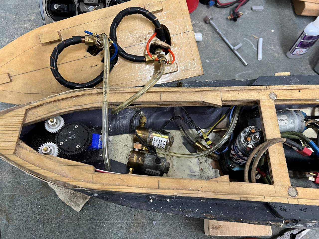
The stern of the loaded ship. The drive motors mounted
wide also allows for the pump motor to sit between them, which is also very
space conserving. The outlet sits on the lower part of the casemate deck but
when it is full battle ready I have another small piece of hose that pushes the
outlet tip further away from the surface of the water. The stern gun solenoids
are wedged in the stern, I don’t have lock downs for these yet but expect that
will be the right thing to do in the future when I have confidence I have the ship
balanced properly. The rudder set up is a single servo directly truing the two
rudders via gears, I think it is 54t to 35t. The stern most deck has slide
latches like the bow piece.
This is the ship partially buttoned up, note the
turrets finally made an appearance! The middle section is meant to hold in
place with the inset magnets but there is also slight tension from the forward
and stern deck pieces squeezing it from front to back as well. Under normal
battle circumstances only this middle section needs routine access.