- Wood Hulls -
I
have seen various resources on wood hull construction. I have built several
wood hulls including cruisers: USS Minneapolis, FN Tourville, RM Duca d’Aosta,
RM Zara. Destroyers: FN Mogador, IJN Akizuki. Capital Ships: SMS Derfflinger, IJN Kongo, IJN Nagato, INJ Yamato. Convoy
ships: IJN Hikawa Maru (x4), IJN Akitsushima, IJN
Chitose, IJN T103. I have also refurbished the IJN Hyuga
and installed wood decks in countless ships of my own and others.
I
have settled into a few techniques over my years of experience that may be
useful to others and wanted to document what is somewhat of a dying art given
the ongoing advancements in 3d printing. This article will show mostly the
building of the RM Montecuccoli, an Italian light
cruiser. The later part will show techniques used on a very different ship, the
Yamato.
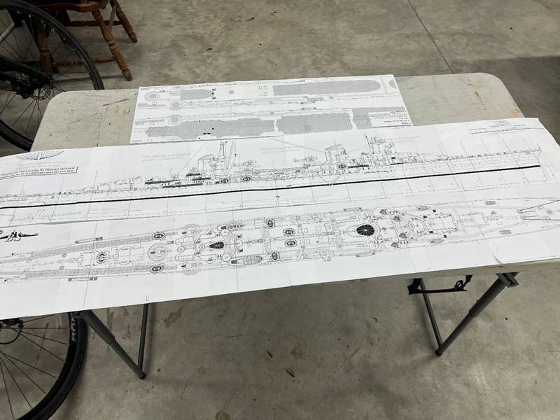
Plans:
A
good set of plans with hull lines is a must. Profile Morskie
is my go-to for high quality plans.
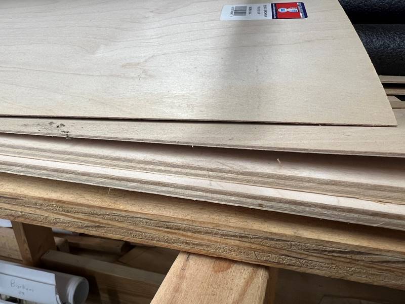
Materials:
Access
to a few different types of wood are required. Most of the structure is built
with 5 ply 1/4 inch thick Birch plywood. The actual deck is commonly 1/8 inch
thick 5 ply Birch plywood. I use balsa wood blocks for water channeling. Some
ships will need 1/32 or more preferably 1/64 inch plywood for modeling the
curved features where you don’t need water channeling. Some ships will do
better with lighter 1/16 inch plywood for decks (destroyers).
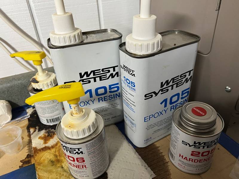
Additionally,
superglue (CA = cyanoacrylate) will be needed to hold things together until a
more rugged binding product like epoxy can be applied to the whole thing. The
most common way to seal wood and fiberglass that I have seen is with a 2 part
epoxy. I have had the best results with West Systems (105 resin along with
either 205 or 206 hardener – they are extremely similar to the point of near
equivalence as far as I can tell), which is somewhat expensive but well worth it.
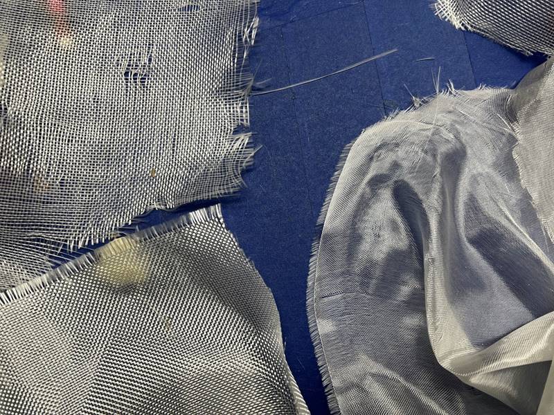
Fiberglass
cloth will also be required, which is measured in “weight,” which is literally
how much a square yard weighs, and is dependent on how thick or thin the
individual strands are and how tightly or loosely woven the cloth is. An
average appropriate “weight” for these purposes is 2-6 oz per yard. The
tightness of the weave is variable based on different products but not usually
very obvious on package labeling. Very heavy and very tight weave is harder to
work with since it is stiffer and won’t conform to curvatures as well. Very
light weight and loose woven cloth will fall apart as you try to handle it.
Also the epoxy doesn’t penetrate the denser/heavier fabrics quite as well
leaving for some soft spots if you are not careful. At the end of the day,
fiberglass cloth is just a textile material that the resin grabs on to and
forms strength, I’ve heard the joke that an old T-shirt would probably work
just fine.
Tools:
Though
one could be creative, a bench top scroll saw is nearly impossible to do
without. A band saw can be helpful but not required. I suppose you could use
hand saws very tediously. Various mechanisms of sanding are also required. I
have a 12 inch benchtop disc sander that I really like, it can handle larger pieces
of wood than the more common 6 inch variety. Some form of had held palm sander
and/or a hand held belt sander is helpful too. A Dremel tool is also nearly a
necessity for most of this hobby.
Make
a plan:
Step
one is to consider the structure of the ship you are building and formulate a
build plan. Are you doing an upside-down build? Is it going to need a
baseboard? Where are cross braces going to be located? Where are the guns going
to be? Where are the important internal components are going to sit? How are
the decks going to come apart for maintenance purposes? You have to make a
decision on how perfectly to scale you want to build. There are some benefits
to making a hull as wide as allowable by the rules (+1/8 inch or 2% allowable
error) and potentially as short as allowable by the rules (-1/2 inch or 2%
allowable error), I would generally recommend going for as close to scale as
possible and allowing the error to be saved for actual building errors. Water
channeling is built into the hull, for large ships between the turrets a
central water line is helpful and bulge water channeling should be part of the
plan. For smaller ships, building material into the bow and stern is typically
enough. Where are you going to place ribs, evenly or clustered in certain areas?
Do you have enough rib lines within the plan set to fill the ship out or do you
have to draw some in 1/2 way between the hull lines you have? How thick are the
ribs going to be width wise? How thick is the subdeck going to be?
Truthfully,
many of these decisions come down to captain preference and are easier to make
with experience. When in doubt, copy what someone else who has a high
functioning ship has done.
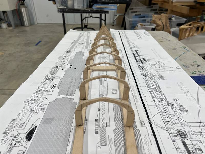
Forming
the basic structure:
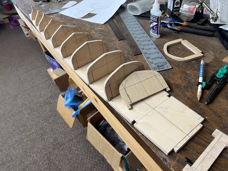
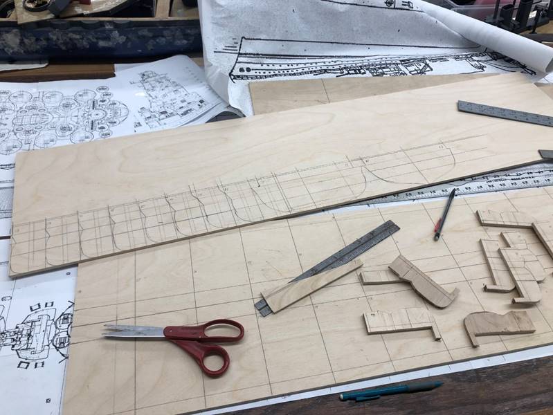
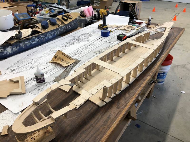
Once
the general plan has been sorted out in your mind and on paper (feel free to
mark up your plan set with pencil) the basic structure of the ship (subdeck and
ribs) can be cut out. Rib lines often come with the front 1/2 of the boat on
the right side and the stern part on the left. Make sure you know where these
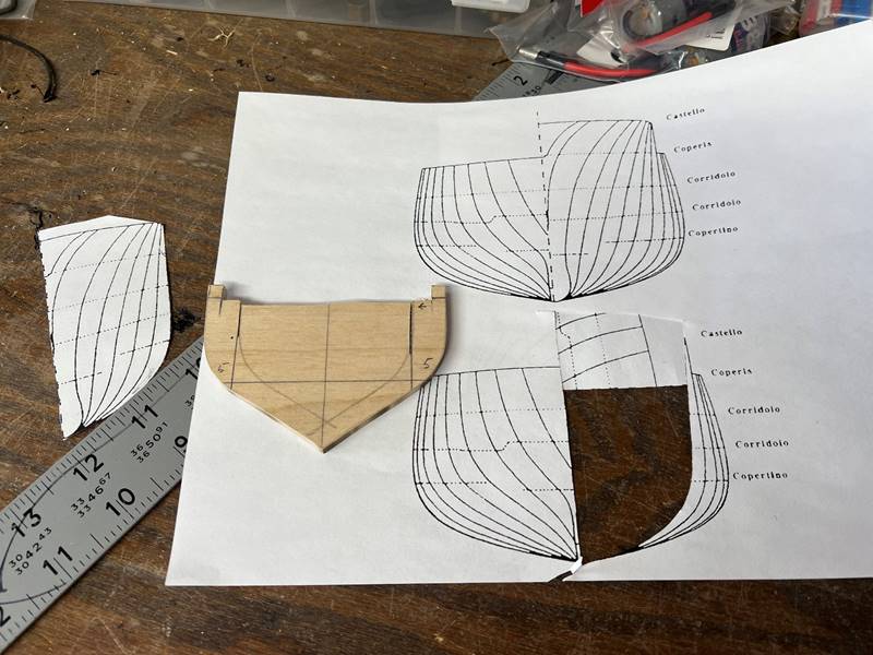
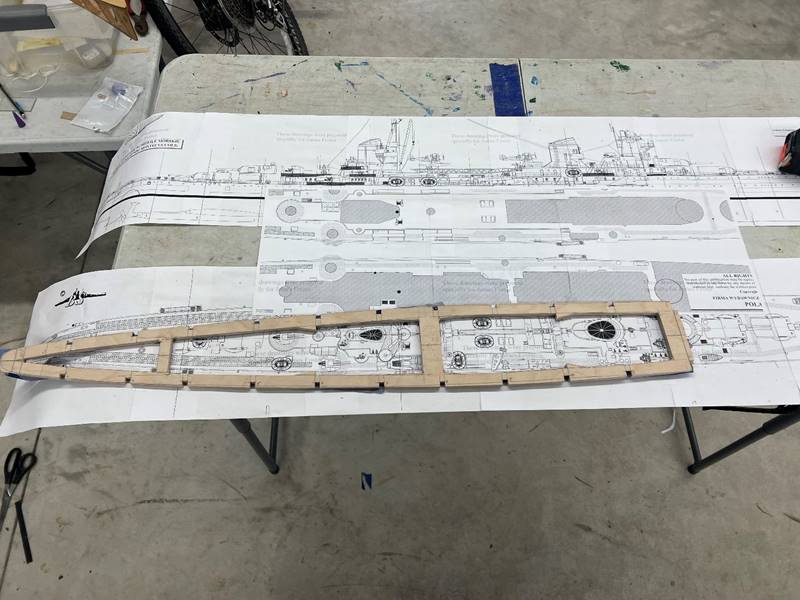
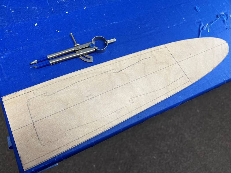
ribs fit into the profile and overhead of the actual ship. This cruiser is
allowed 17 ribs (with 2 inches in bow and 1 inch in stern hard area) and has
just the right amount of hull lines available. I typically either digitally
flip the image before printing to make the rib whole, or cut out the half rib,
trace it, then flip it on its vertical center line while I am working. Having
lines marked with the water line or at minimum 1 inch below the waterline is
necessary. Be sure to label the rib numbers as you go. Also, the actual height
of all of the traced ribs needs to be 1/8 inch lower than the plans to account
for the eventual placement of the deck on top of the subdeck. The ribs are also
notched to mesh with the subdeck, and the subdeck will be notched to fit the
rib accordingly. There is debate as to whether to leave the outer edge of the
ribs or the outer edge of the sub deck. I’ve heard the opinion that the outer edge
of the subdeck should be left in tact for strength,
but I don’t think it matters that much, there will be plenty of structural
integrity and I have never had a rib slip laterally.
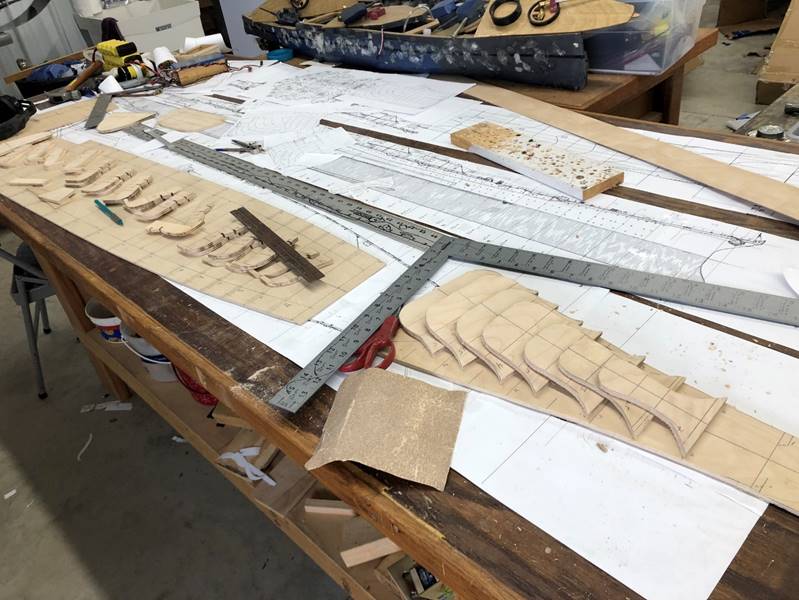
I
similarly trace the subdeck from the plans after drawing the center line, just
drawing 1/2 of the ship, then flipping the plans to ensure greater symmetry.
Then I draw in the locations of the ribs and edge of the sub deck, the
locations of the cross braces and deck latch holds. The outside of the sub deck
is notched to accept the ribs. I cut and sand the outer edge to be slightly
wider than the pencil line, to allow for more finishing sanding later. I trace
the width of the sub deck with a compass. In small ships 1/2 to 3/4 inch should
suffice, this ship has a 5/8 inch subdeck. Larger ships with wider beams and
thus more ability to access the internal portions when assembled will get wider
subdeck to allow for more strength and more of a water seal, I commonly use 1
inch. I typically drill out any sharp turns with a 1/8 inch or 1/4 inch drill
bit to allow the scroll saw not to over cut.
Throughout
the process I will line up the ribs into the subdeck to be sure alignment is
proper.
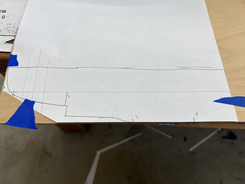
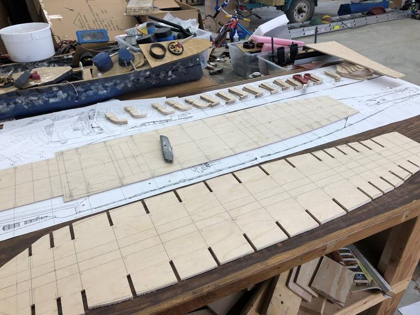
To
make sure the contour of the bow and stern are proper, trace from the profile
plans the shape and build a small section of keel. Some prefer to build a keel
the entire length of the ship however, when using the upside-down build method
this is not required amidships but is useful at the bow and the stern. On most
ships I use 1/4 inch plywood for a keel. Since this is a small light ship I am
using 1/8 inch keel only in the far stern and bow. The ribs and keel need to be
notched to fit each other. I commonly leave a bit of wood to subdivide the ship
and serve as some overlap in the internal armor because the extreme bow and
stern can be hard to fit the internal armor flush.
As I
cut and sand the ribs first from the outside shape, then marking the thickness
with a protractor and cutting out the center to keep the (in this case) desired
1/2 inch thickness/width of the rib. The portion of the rib which will serve as
the bottom part of the hull will ultimately either be sanded very thin or
completely removed in this style of build, and as such I cut them very thin to
start with. Continuing to check alignment throughout the process with hopefully
help catch any mistakes before you glue everything together.
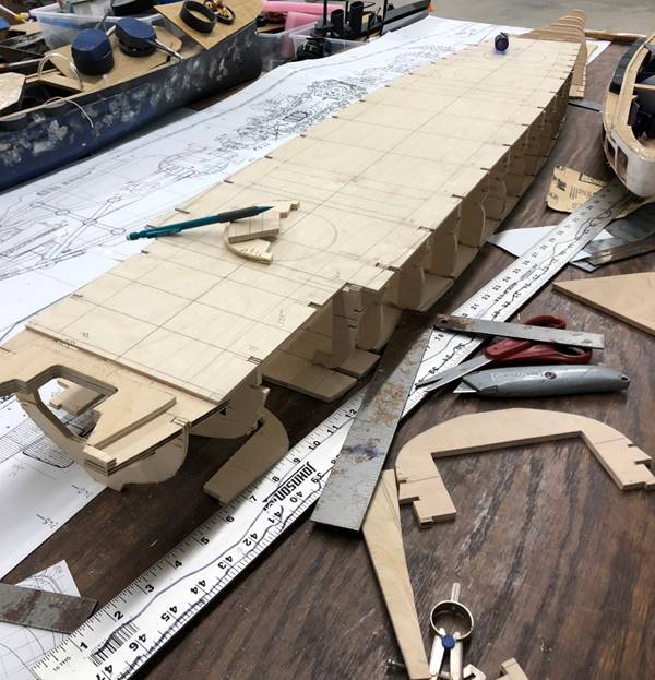
A
higher level technique that I have learned through experience is to notch the
ribs where the edge of the open window meets the top edge of the hull hard area
in order to allow for the side of the ship to maintain a flush contour rather
than an awkward lip.
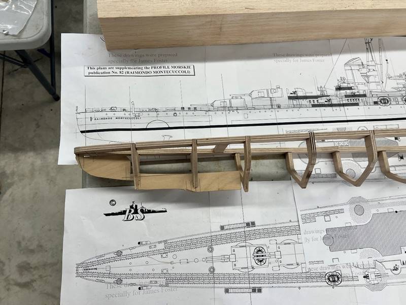
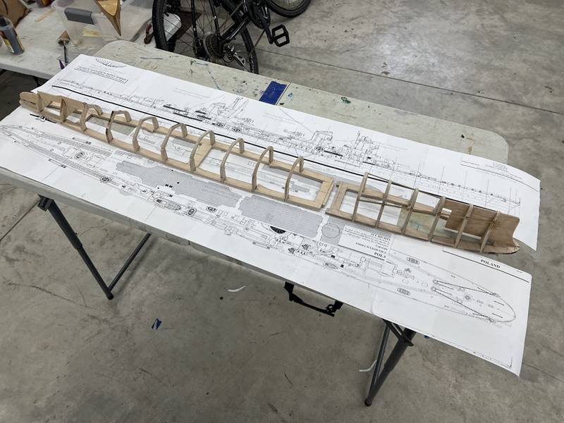
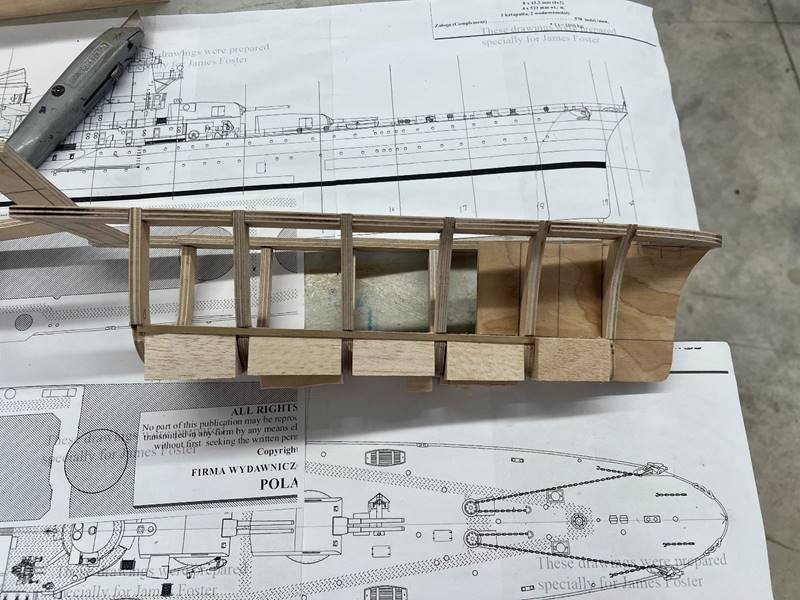
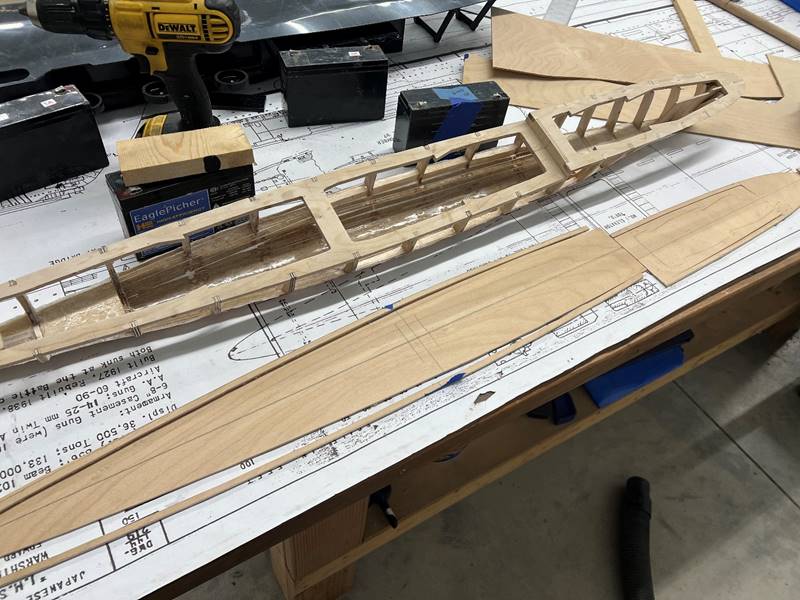
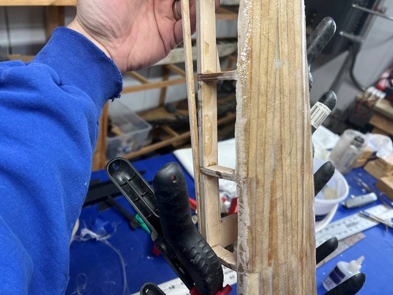
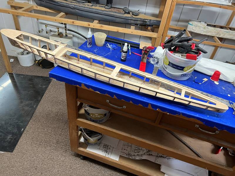
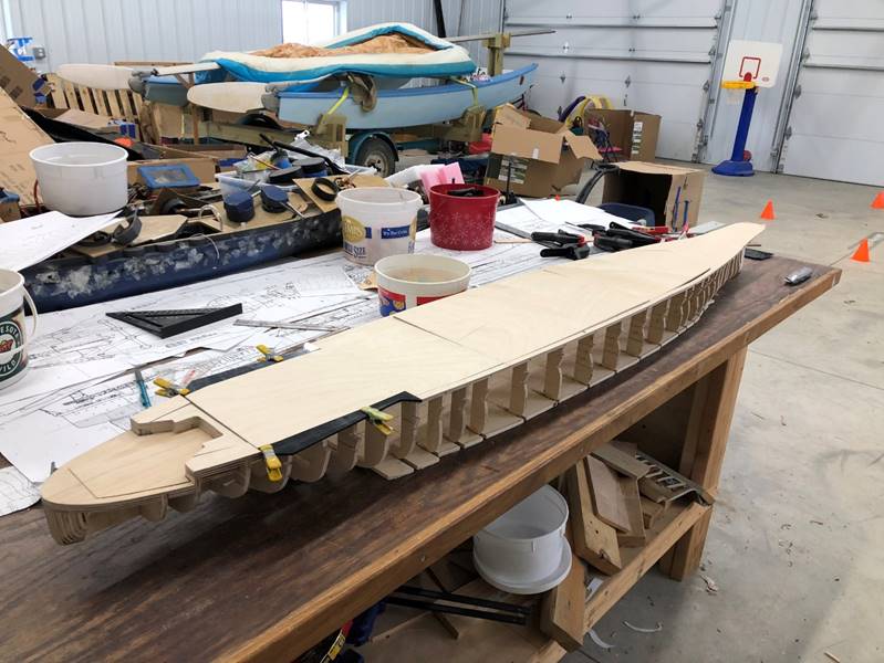
In
step deck ships I will typically build the bow and stern sections somewhat
independently then assemble them together later. With the ribs glued into
position, I inserted a strip of the very thin plywood (1/32 or 1/64 inch) at
the border of the impenetrable window. Then cut chunks of balsa wood to fit the
gaps, this will all be sanded smooth later.
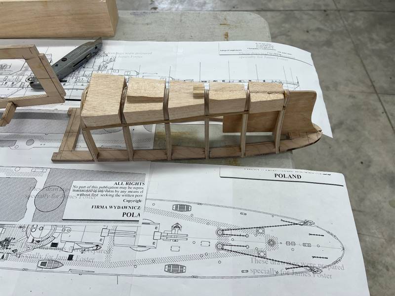
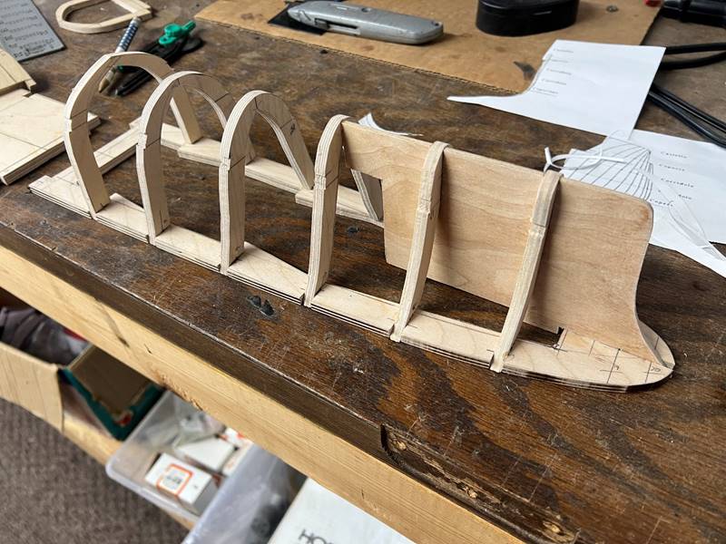
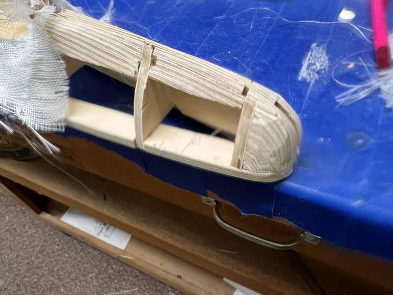
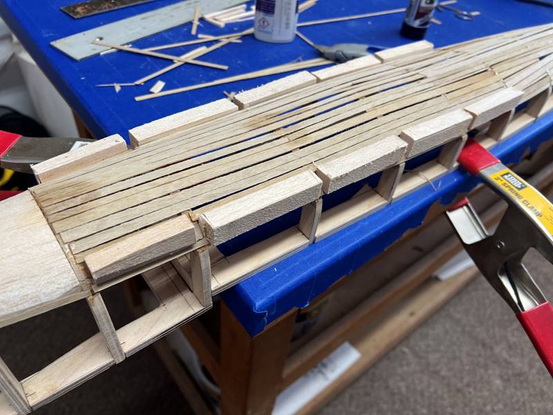
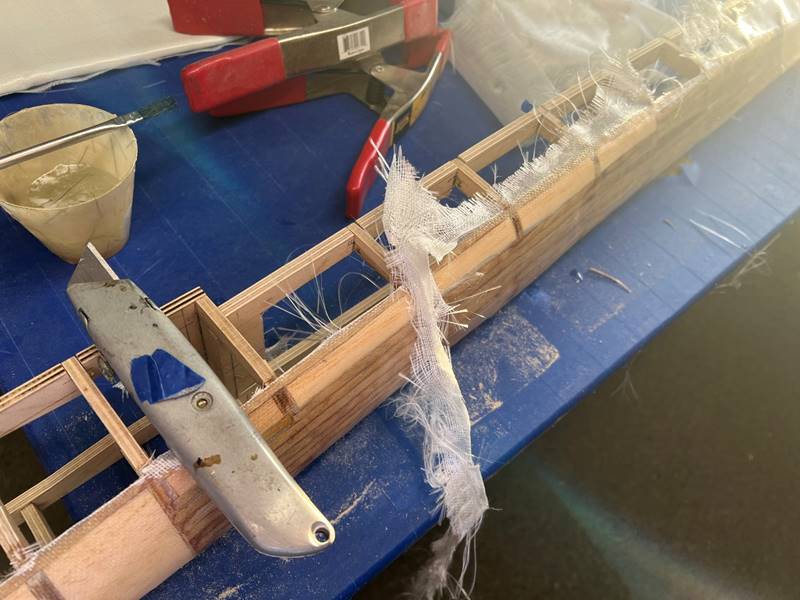
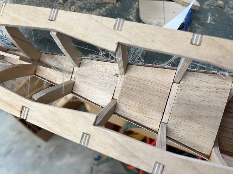
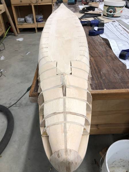
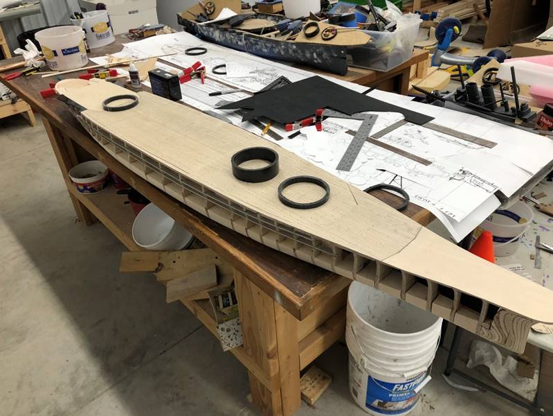
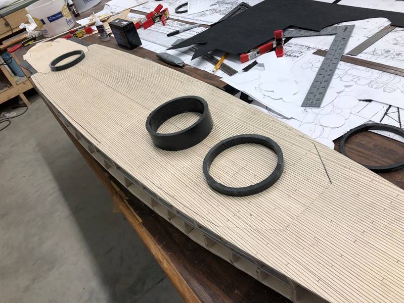
Adding
balsa for water channeling and shaping the curves:
Because
the extreme bow of the ship will be nailed by incoming fire repeatedly, I have
changed the approach of building this out of balsa and covering in fiberglass
to just building it out of ply wood to begin with. I layer plywood in place and
sand them to shape. This picture shows a rough sanding of the bow that will be
smoothed out later. This is also a good look at the sanded balsa for the
adjacent sections. The same process is used for the stern. In this ship because
it becomes extremely narrow in the stern I opted just to use layered plywood
for the 2 stern most sections, and balsa wood in front of that, usually I would
only do the stern 1 inch hard area with ply wood.
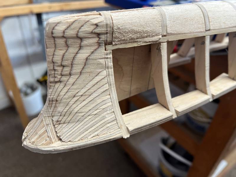
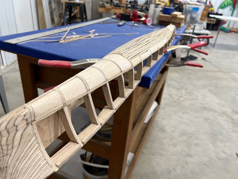
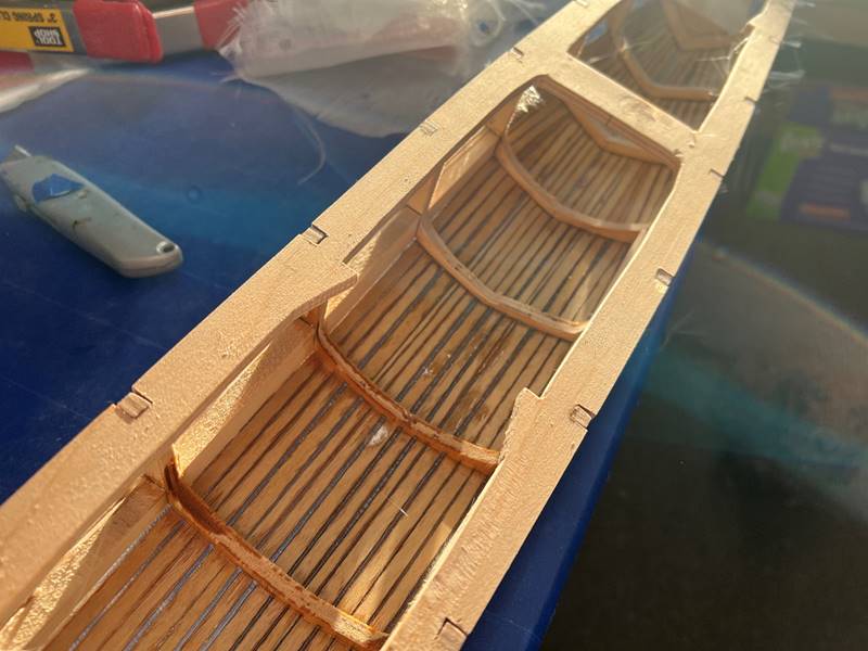
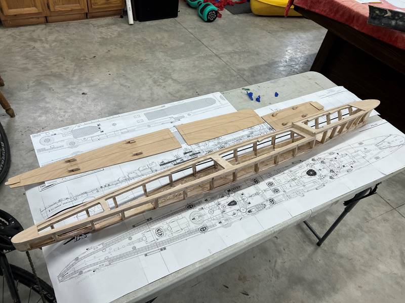
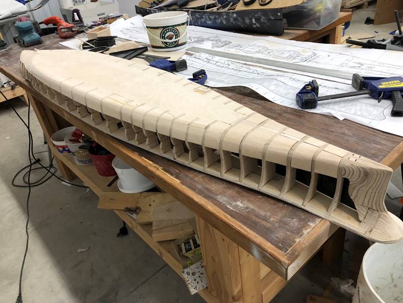
Planking
the bottom:
In
most small ships, bilge water channeling is not required. I opted to use some
balsa in the width of the midships in this ship to try to min/max, though it is
probably not adding much survivability or stability. The way the upside-down
build method works out now becomes pretty obvious. I have clamped the ship to
the work bench and will fill out the bottom of the ship (I don’t always clamp
it down but I wanted to see if it would help keep things from warping. To form
the contour of the middle part of the ship, I am using some combination of 3/16
up to 1/4 or so wide strips of the very thin (1/64 inch) plywood and gluing
them to the ribs. Once the bottom of the hull is built out, I again sand it all
smooth. There will be a small ridge at the transition from the wood planks to
the balsa, I typically will do an extra layer of fiberglass cloth over the
balsa portion to smooth things out.
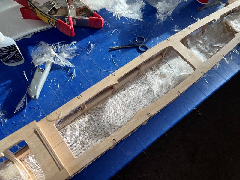
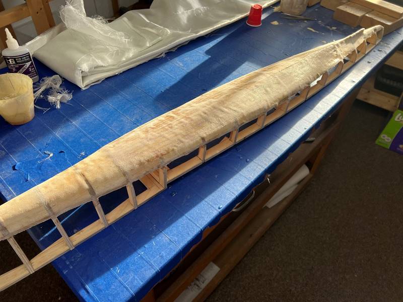
Fiberglass:
The bottom
of the ship is now ready for fiberglass. There are many different ways I have
don’t this over the years. Generally 3 layers of lower weight fiberglass should
be sufficient, this ship is built with 1.75 oz cloth but up to 3-4 oz is
probably OK, I would use up to 5 or 6 oz cloth on heavy capital ships that
don’t require attention weight considerations (Yamato). It is best to overlap each
layer of fiberglass so the mesh isn’t always at 90 degree angles to each other
in order to provide higher strength. In the picture below the middle section
shows how I have cut at 45 degree angles the strips of fiberglass cloth. The
layer next to the ship is to go on right over the top. Ultimately I did a 3rd
layer as well at a slightly obloquie angle (probably 15 degrees). The most
correct way to do this step is one layer at a time with full cure and sanding
between layers. Since the cloth I was using was very light and permeable, I
opted to do all 3 layers while wet and it went pretty well. Regardless, some
amount of sanding and refinishing is going to be required.
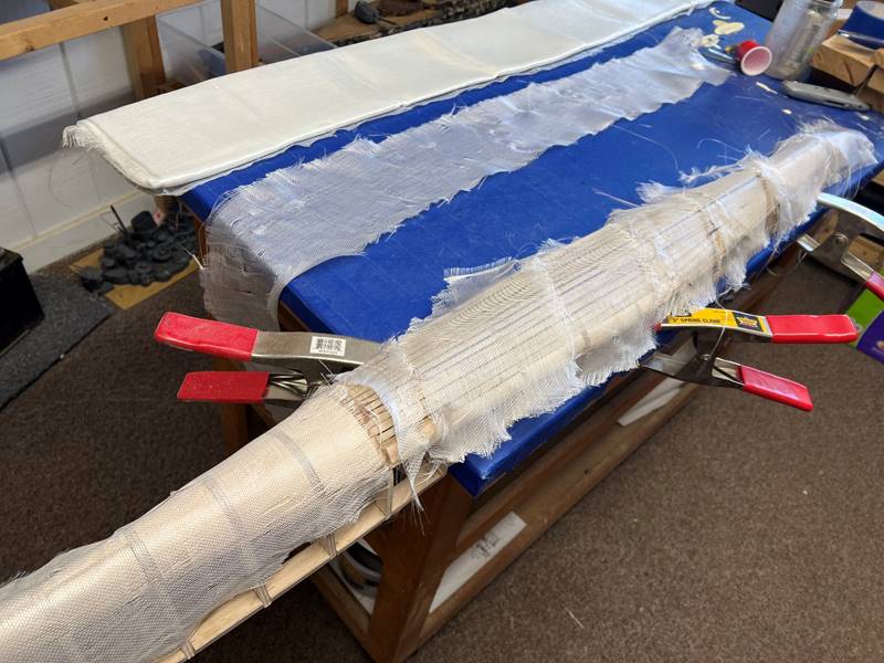
The
excessive fiberglass can be easily trimmed back with a knife and/or sanded.
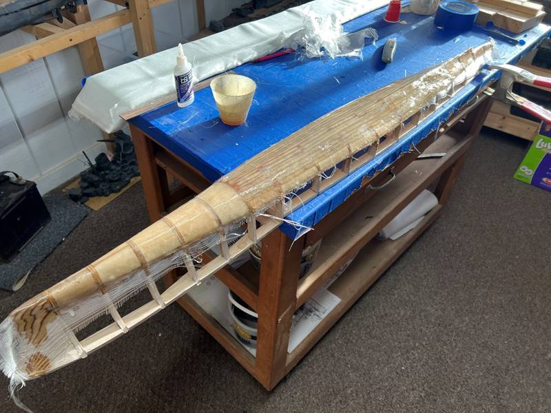
Next
I flipped the ship upright. The remaining interior component of each of the
ribs is sanded out carefully. With this view, it is recognizable how little the
bulge water channeling is likely to add to this ship.
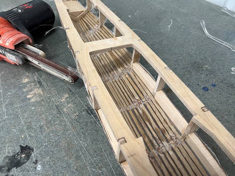
In
the far bow of the ship, I would usually just leave the ribs level across at
the water line, I cut the mid sections out and back filled with balsa on this
ship to save weight.
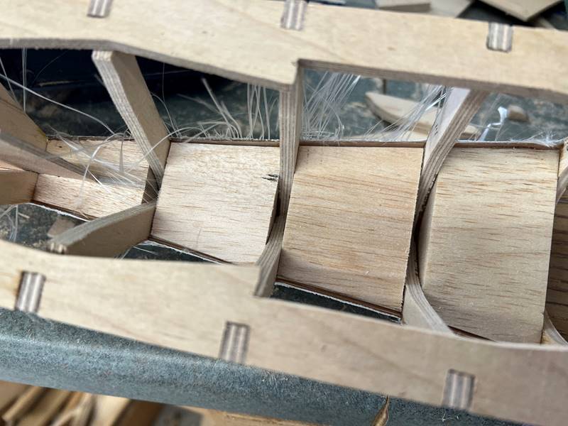
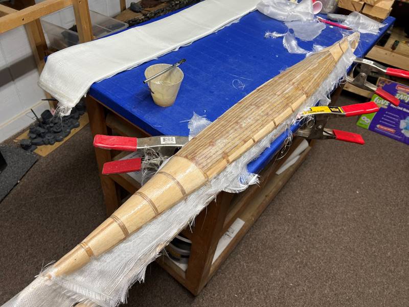
In
order to get maximal strength into the otherwise weaker part of the ship, a
layer (some times two) of fiberglass cloth is epoxied
into the bottom inside of the hull. This is a good time to fill in any small
cracks or gaps with epoxy. The top exposed part of the balsa (water channeling
in bow/stern/bulges) needs to be protected with fiberglass cloth/epoxy as well,
so that incoming bb’s don’t imbed themselves into the ship.
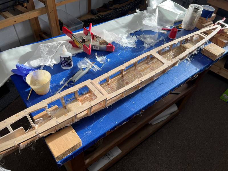
After
it dries, I trim the loose edges and sand any rough spots.
I
wasn’t happy with the total thickness and rigidity of the bottom of the hull so
opted to add a fourth layer of fiberglass (all 1.75 oz per square yard for a
total of 7 oz per square yard of material). Again, the benefit of many layers
is that you can overly the meshwork of the fibers at different angles to get increased
strength.
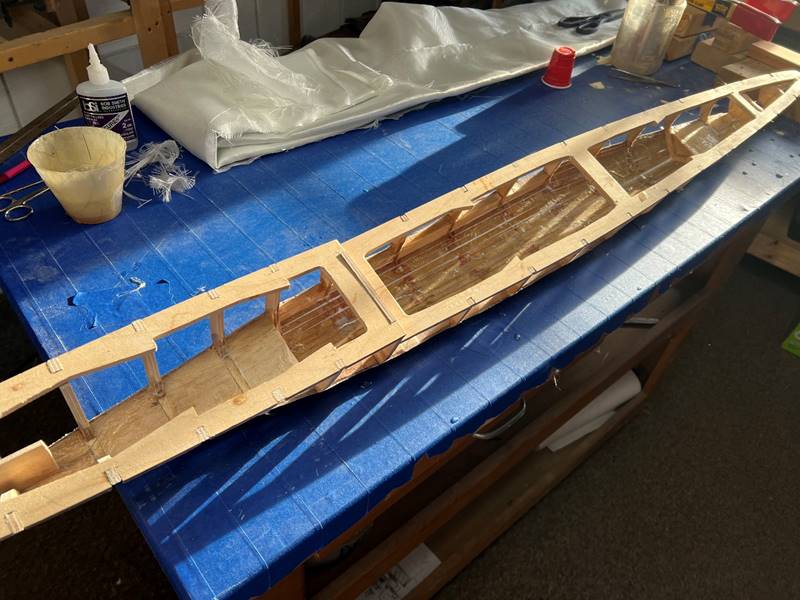
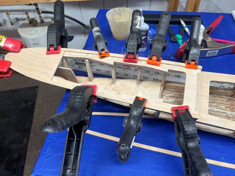
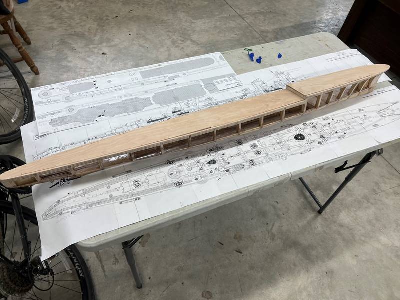
Back
to working on the deck itself. By now, I will have sanded the outer edge of the
subdeck/rib fairly flush. Simply tracing the outer edge of the subdeck on to a
1/8 ply wood sheet and cutting those sections out works well. I typically try
to remember that the pencil line itself has width, and cut close with a scroll
saw, then sand to the outer edge of the width of the pencil line. Eventually
sanding the whole thing flush after the outer ridge of the deck is glued in
will be done.
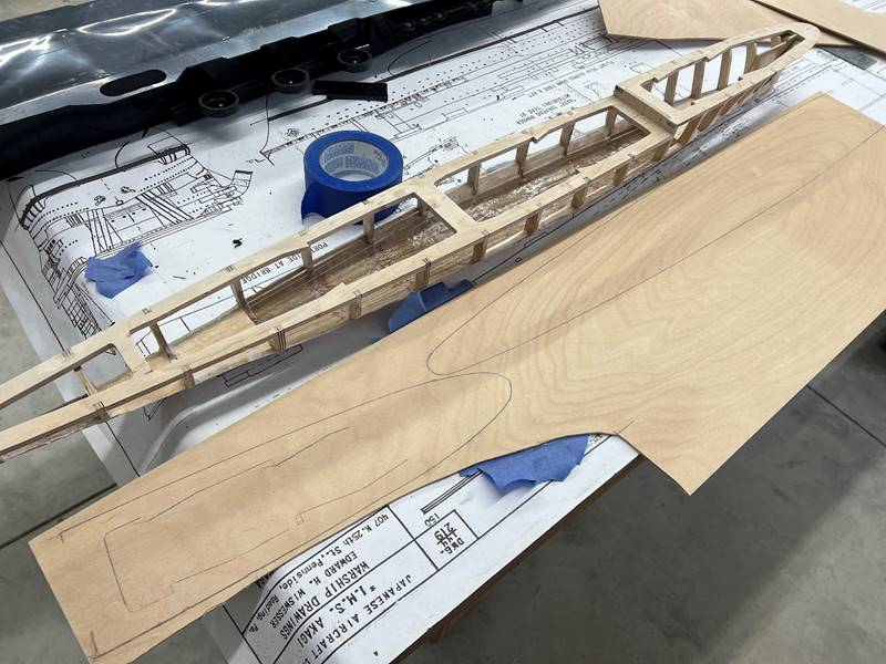
I
use a compass to set the width of the outer deck rim to typically about 1/4
inch wide and trace along the outer edge. Then use the scroll saw to cut it
out. The far bow and far stern can be cut flush width wise for most ships.
Again, determining where these cuts and where any additional deck cuts go has
usually been previously determined prior to this step.
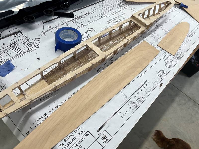
After
cut, the outer edge of the 1/8 inch deck is glued to the subdeck with super
glue. I commonly glue this sequentially, clamping as I go, so that I can
control the exact placement of the somewhat flimsy 1/4 inch strip. Another “pro
tip” is to sand the actual deck piece very slightly (trying to remove only 1/32
inch) to allow the eventual epoxy layer to not cause the decks to bind too
tightly. The deck pieces are also fit with the slide latches at about this
point. Typically, any exposed wood will require 2 layers total of epoxy,
because of the nature of the 3 dimensional structure, it will take multiple
different sessions of brushing on epoxy and sanding.
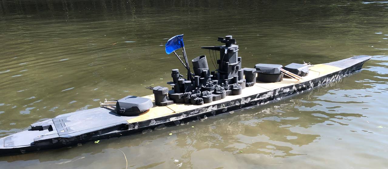
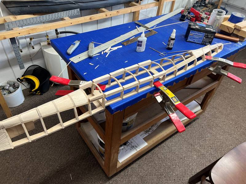
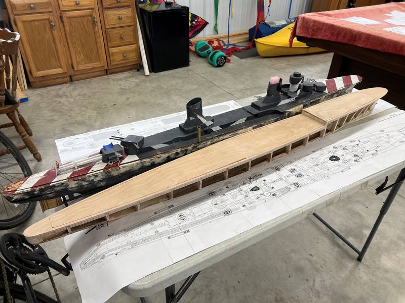
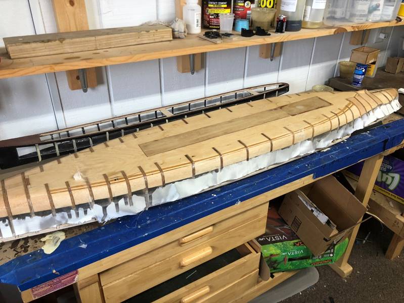
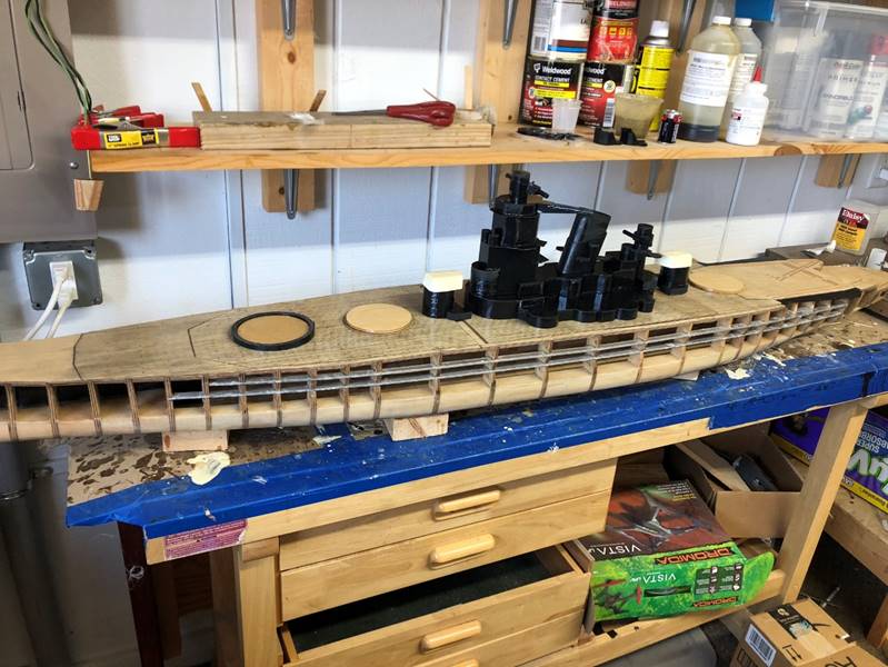
The
process of building the wood hull is at this point completed and the ship can
be built out similarly to any other ship. Here she is next to her younger
sister, the Duca d’Aosta.
----------------------------------------------------------------------------------------------------------------------------------------------------------------------------------------
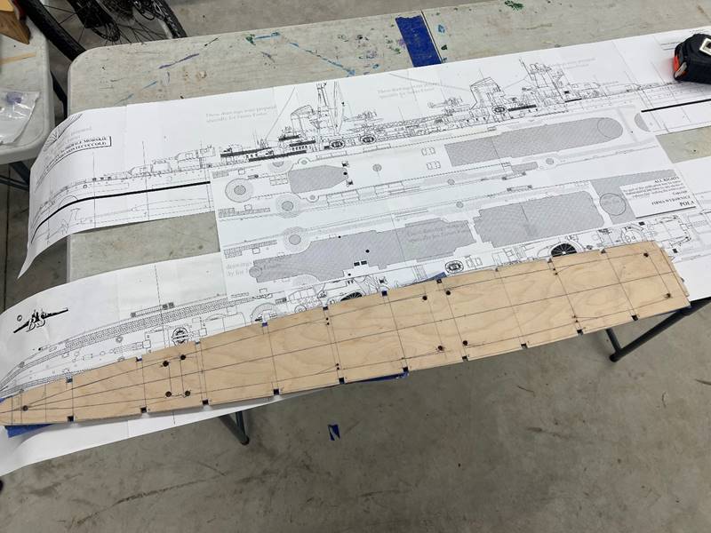
To
show a slightly different technique (using a baseboard) I will show how the
Yamato came together. Tracing, cutting out, and fitting the ribs and subdeck
are very similar steps. The far bow and stern ended up coming together more
like the “upside-down” build, and in these sections a full rib piece was built
for each. For the baseboard section I opted to only use the outer edge of the
ribs as the center would be cut out any way, and it would save a ton of wood
given the width of the Yamato, though this is potentially more confusing and
more attention to alignment will be needed. Each of these partial ribs are
inset into the baseboard and subdeck, just as the
would have been if they were an entire rib piece. 1/4 inch 5 ply birch plywood
is used for all of these parts except the mid section
subdeck, which is 1/8 ply wood - this ship has stringers such that only a 1/2
inch total deck thickness is allowed (1/8 inch for sub deck and 1/8 inch for
deck).
A
baseboard is a flat piece of 1/4 inch ply wood that forms a ridged bottom for
the ship. Larger ships benefit from the structural integrity and the added
weight isn’t as problematic. Each rib is cut to fit both into the baseboard and
the subdeck. A water channel is also cut out of the center of the baseboard.
The
far bow in most of my ships is completely sealed because you rarely need to use
that space, and the internal space isn’t all that usable any way. The front,
midships, and stern portions which were all built separately were eventually
glued together. The sub deck was cut with braces to leave open areas to access
the internal parts of the ship. Then the ribs were glued in to both the sub
deck and the baseboard. You can see the excess baseboard that extends beyond
the edge of the rib that will need to be cut back/sanded. The decks are 1/4
inch ply wood with cuts to over lap a support beam.
The width of the outer most lip of the deck in most of my builds is commonly
1/4 inch to 3/8 inch depending on the size of the ship and width of the subdeck
seal.
Balsa
wood is a perfect material for building up bow, stern, and bilge water channeling.
It is very easy to work with, displaces water (though needs to be sealed) and
is light. It is cut to fit between the ribs and glued in. Then sanded smooth along
the outer edges.

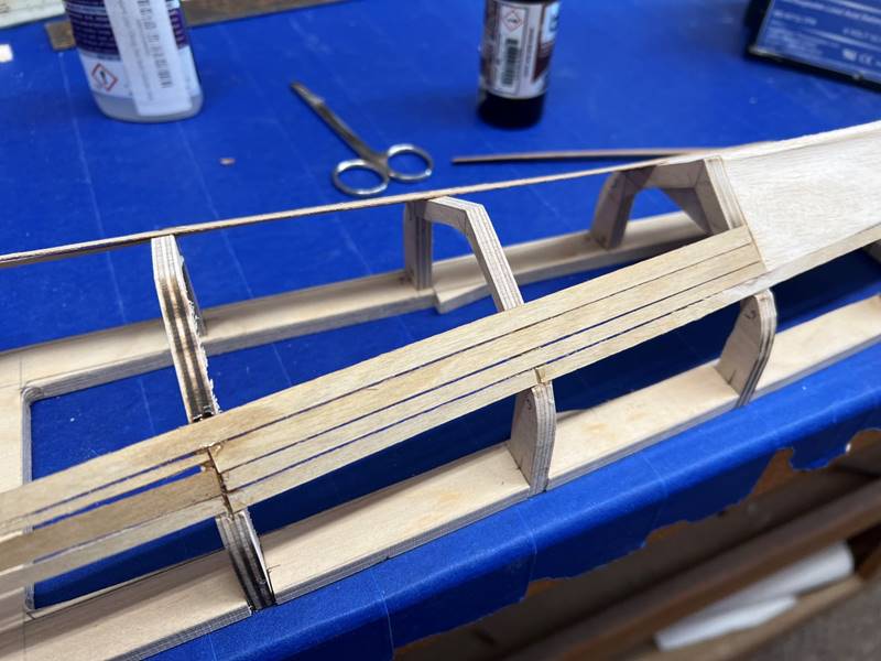
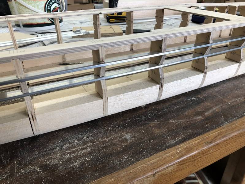
This
ship had a complex shape to the armor belt, allowing for “stringers” to be
built into the hull within our hobby so that the structure and shape of the
hull will be maintained when covered with the thin balsa wood sides. I have
been making the stringer out of aluminum bars 1/8 inch thick. I cut both the
rib and the aluminum to accept each other. The trick is to cut the 1/4 inch
slits in the aluminum slightly wider than 1/4 inch, this allows you to bend the
metal at those now weakened points with your hands (or vice) which allows it to
take the curved shape of the side of the hull as necessary. The far bow and far
stern transitions from balsa to plywood for additional BB resilience.
Marking
lines in pencil for the deck is of course optional but usually looks really
good.
The
fiberglass layering on the bottom of the hull is similar with any wood build. I
overlayed the entire thing with 5oz cloth and west systems epoxy. I did 2
layers of fiberglass and sand/smooth re-finish with epoxy 4 total times (2 with
the fiberglass and 2 as finishing). Before the epoxy/fiberglass layer the
midline bottom of the ship was cut out for a water channel, then I routed out a
lip and inset a very thin piece of ply wood that was sanded smooth with the
bottom of the hull. Essentially every part of the ship (except aluminum) needs
a minimum of 2 layers of epoxy, a light sanding between layers will allow it to
stick better, heavy sanding to any defects and bubbles to smooth it out.
Finished Product: